Worm Gear Ratio and Calculation — Formulas, Examples, Real Cases
The arithmetic behind a worm and worm wheel pair, three worked examples, and the integer-tooth reality that ruins clean textbook ratios.
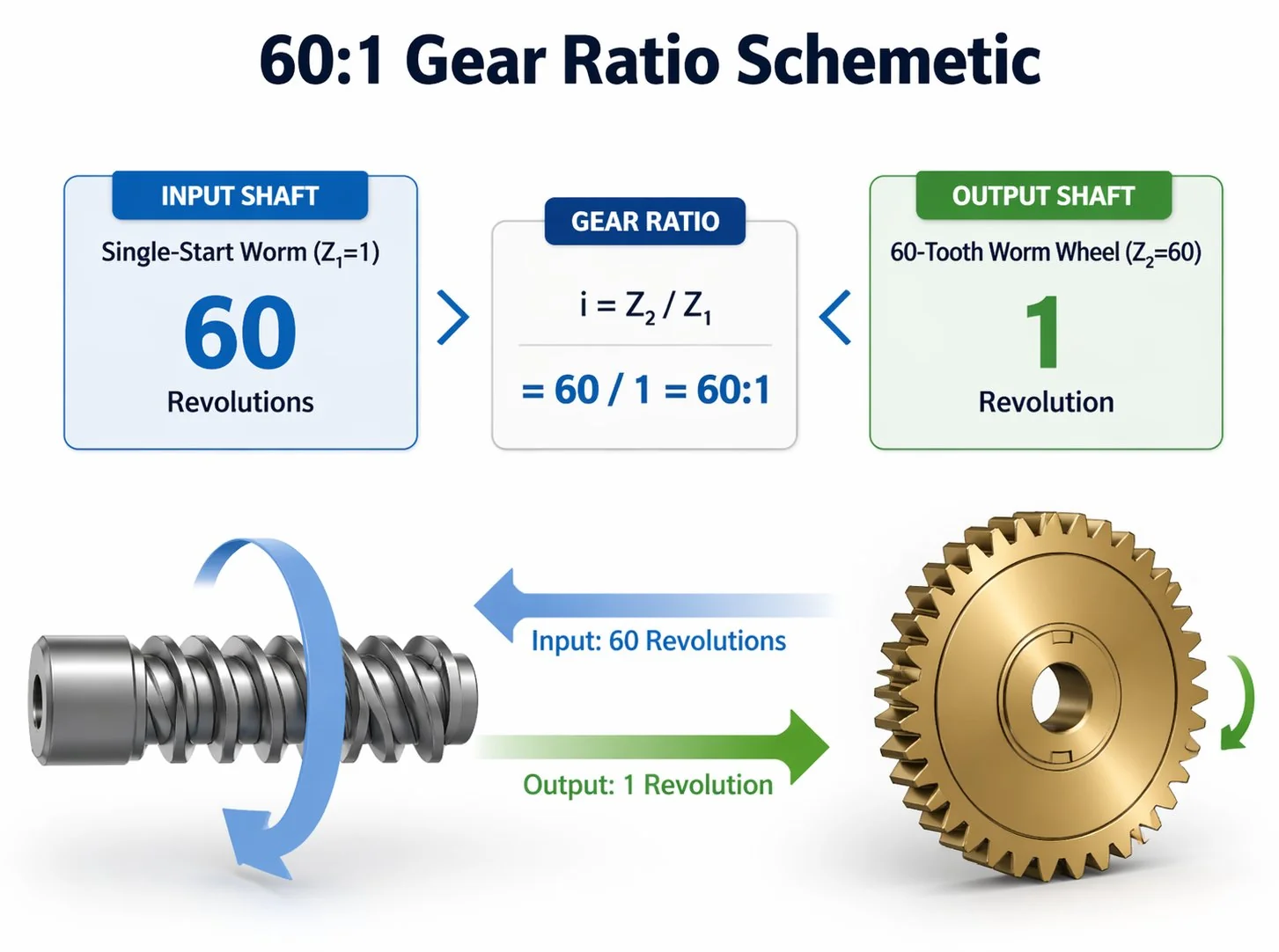
Worm gear ratio is the number of wheel teeth divided by the number of worm starts: i = Z₂ / Z₁. A single-start worm meshing with a 40-tooth wheel gives 40:1. A 4-start worm on the same wheel gives 10:1. Efficiency is governed by lead angle and friction angle through η = tan(λ) / tan(λ + φ) — typically 60 to 70 percent for high-ratio single-start drives, 85 to 92 percent for low-ratio multi-start drives. Required input torque equals output torque divided by (ratio × efficiency), and integer tooth counts mean the ratio you actually get is rarely the clean number you typed into the spec sheet.
The two formulas every worm drive comes back to
Forget the long lists of pitch and module equations for a moment. Two formulas determine 90 percent of the design decisions on a worm and worm wheel pair, and most calculation mistakes in the field come from misapplying these two — not from advanced geometry.
Formula 1 — Reduction ratio (kinematic)
i = Z₂ / Z₁
Where Z₁ is the number of worm starts (1, 2, 3, 4, sometimes 6) and Z₂ is the number of wheel teeth. This is pure geometry — material and lubricant do not enter the equation.
Formula 2 — Mechanical efficiency
η = tan(λ) / tan(λ + φ)
Where λ is the lead angle of the worm (function of starts and worm pitch diameter) and φ is the friction angle of the contact (5 to 8 degrees for well-lubricated steel-on-bronze, 10 to 15 degrees for poor lubrication). This is where material, surface finish, and lubricant chemistry enter the picture.
The reason these two formulas matter so much is that they capture the central trade-off of worm gearing — high ratio means low efficiency, low ratio means high efficiency, and you cannot have both in the same set. The second formula explains the first one’s hidden cost.
Reading the ratio formula correctly
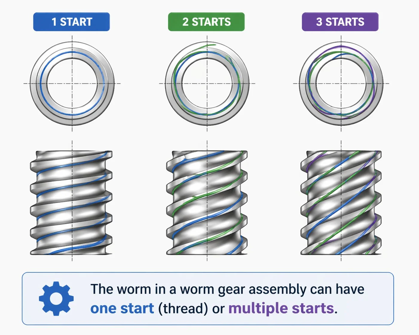
Z₁ counts the number of helical thread starts on the worm — not the total number of thread crests visible at any one circumferential position. Look at the worm end-on. A single-start worm shows one thread spiralling down the shaft. A 2-start worm shows two threads winding in parallel, offset 180 degrees. A 4-start worm shows four parallel threads at 90-degree spacing. The visual cue is the number of separate threads you can trace from one end of the worm to the other.
Z₂ counts wheel teeth in the conventional way — total tooth count around the wheel circumference. A 40-tooth wheel has 40 teeth. The number is integer by physical necessity; you cannot have 40.5 teeth.
The integer trap that ruins clean textbook ratios
Both Z₁ and Z₂ must be integers, and that constraint matters more than most calculators acknowledge. If a customer asks for “exactly 35:1,” our engineering desk has to tell them they will get one of three nearest practical ratios: Z₂ = 35 with Z₁ = 1 gives 35:1 exactly, Z₂ = 70 with Z₁ = 2 gives 35:1 exactly, or Z₂ = 36 with Z₁ = 1 gives 36:1 (a 2.9 percent overshoot). The choice depends on what else the application needs — Z₂ = 35 is fine for a single-start drive, Z₂ = 70 doubles the wheel diameter at the same module, and Z₂ = 36 is a small compromise that lets you use a more common wheel size.
Asking for 35.5:1 simply does not work — there is no integer pair that delivers exactly that ratio. The clean number on the design sheet has to round to something the factory can actually cut. For Korean and Japanese OEM applications where downstream encoders and motor controls assume an exact gear ratio, this rounding has to happen at the design stage, not after the parts are made.
How efficiency follows from lead angle
The lead angle λ is the angle between the worm thread helix and a plane perpendicular to the worm axis. For a single-start worm with small pitch diameter, λ might be 3 to 5 degrees. For a 4-start worm with the same pitch diameter and module, λ climbs to 15 to 20 degrees. The relationship is geometric: more starts at the same module means a steeper helix.
Plug numbers into the efficiency formula and the trade-off becomes concrete. Assume a friction angle φ = 6 degrees, which is realistic for well-lubricated steel-on-phosphor-bronze:
The shape of the curve matters. Going from 3° to 10° lead angle nearly doubles efficiency. Going from 20° to 30° barely moves the needle. The sweet spot for high-efficiency multi-start drives sits around 15 to 20 degrees lead angle — beyond that you get diminishing returns and you start losing the wheel face width that makes the drive serviceable. Most catalogue worm and worm wheel pairs sit in two clusters: 3 to 5 degrees (high-ratio self-locking) or 12 to 18 degrees (medium-ratio efficiency-driven).
A trap I see often: a designer reads “η = 70 percent” off a manufacturer’s catalogue and treats it as a constant for sizing the motor. It is not. The 70 percent figure is the rated efficiency at rated load and rated speed. At one-tenth load, friction torque inside the gearbox stays roughly constant while useful torque drops by ten — measured efficiency can fall below 30 percent. Always size for the actual operating point, not the nameplate. If you only have light loads in the duty cycle, the percentage you should plug into the input torque calculation is the part-load number, not the catalogue number.
Worked example 1 — Conveyor belt drive
A flat-belt conveyor moves 80 kg of product at 0.5 m/s along a 40 m line. The drive pulley is 200 mm diameter. The customer wants intermittent duty (40 percent on, 60 percent off) and a quiet drive. Self-locking is not required because the belt is horizontal.
The walk-through below shows every arithmetic step from belt force to motor selection. The same procedure works for any conveyor sizing exercise — the only thing that changes is the input numbers.

Notice the rounding decision at step 5 — the exact arithmetic ratio is 29.4:1, but the nearest practical integer-tooth ratio is 30:1, which gives a slightly slower belt speed. The customer accepted that compromise without a visible difference at the conveyor output. This is normal for industrial drives.
Worked example 2 — Hoist drum drive

A small workshop hoist lifts up to 500 kg on a 100 mm radius drum. Lifting speed is specified at 6 m/min. Self-locking is mandatory because a falling load would be a safety hazard. The customer wants to use a standard 1,400 rpm three-phase motor.
Self-locking eliminates multi-start worms — we are forced into a 1-start design with a low lead angle, accepting the efficiency penalty.
Two things stand out from this calculation. First, the efficiency penalty for self-locking is substantial — about 67 percent of input power becomes heat in the drive. Second, the motor power requirement (3 kW) is much higher than the same load would need in a high-efficiency helical right-angle reducer (perhaps 1.5 kW). The customer is paying for self-locking with extra electricity over the lifetime of the hoist. For a workshop hoist running maybe 200 hours per year, that trade-off is acceptable. For a 24-hour production hoist, it would not be — the right answer there is helical reducer plus a separate mechanical brake.
Worked example 3 — Indexing rotary table
A 4-station indexing table positions automotive seat-frame welding fixtures. Each station holds 12 kg, total table mass 80 kg, table radius 400 mm. Index time per station is 1.2 seconds (90 degrees rotation). Holding torque between motions must resist accidental nudge but the drive itself is electrically held by a servo brake — self-locking is desirable but not mandatory.
This calculation is dynamic, not static. The dominant load is acceleration of the table mass through 90 degrees in 1.2 seconds — peak torque happens during acceleration, not during steady rotation. Servo applications also need lower backlash than the conveyor or hoist examples.
The acceleration profile assumes a triangular velocity ramp — first 0.6 seconds accelerate, last 0.6 seconds decelerate. Peak angular velocity at midpoint is 2 × 0.785 rad / 1.2 s = 1.31 rad/s. Peak angular acceleration is 1.31 / 0.6 = 2.18 rad/s².
The takeaway: dynamic indexing applications drive the calculation through acceleration torque, not steady-state torque. The polar moment of inertia of the table itself often dominates over the workpiece mass, especially on heavy steel rotary tables. Servo selection has to satisfy peak torque, not mean torque — failing this is the most common reason indexing prototypes stall during the first cycle.
Common calculation mistakes that destroy designs
Confusing Z₁ and Z₂. A surprising number of first drawings arrive with worm starts and wheel teeth swapped — somebody wrote the wheel tooth count where the formula expects the worm starts. The result is a calculated ratio of 1/40 instead of 40, which makes the math look absurd and stops the design dead. Always label clearly: Z₁ for the worm, Z₂ for the wheel.
Forgetting to divide by efficiency. The basic ratio gives you the kinematic relationship between input and output speeds. Translating that to torque requires dividing by efficiency. Skip the efficiency divisor and you specify a motor that is far too small. The drive will stall under nominal load. Input torque = output torque ÷ (ratio × efficiency), always.
Treating efficiency as a constant. The published rated efficiency is at rated load. Light-load efficiency is much lower because the friction torque inside the gearbox stays roughly constant while useful torque shrinks. Always use the operating-point efficiency, not the headline number.
Using static torque for dynamic applications. Indexing tables, hoists with shock loads, and any drive with frequent start-stop cycles must be sized for peak acceleration torque, not steady-state torque. The peak can be 2 to 4 times the steady value depending on cycle time.
Demanding non-integer ratios. Asking for 47.3:1 has no solution. Round to the nearest practical integer-tooth ratio at the design stage. If the controller downstream needs an exact ratio, design the gear ratio first and let the controller scaling adjust to the actual ratio.
Forgetting service factor. A drive sized exactly to the calculated nominal torque has zero margin for line voltage variation, ageing, occasional overload, or thermal cycling. Apply a service factor between 1.3 (light intermittent) and 2.5 (heavy shock-loaded) before selecting the motor and gear set.
Frequently asked questions
Q: Is gear ratio the same as reduction ratio?
For a worm and worm wheel pair where the worm is the driver, yes — gear ratio i = Z₂/Z₁ equals the speed reduction ratio. The output shaft turns once for every i turns of the input. In rare layouts where the wheel drives the worm (back-drivable multi-start designs used as overrunning clutches), the gear ratio formula stays the same but the kinematic interpretation flips. Worm-driving-wheel is the standard case and the only one that needs unambiguous treatment.
Q: How is lead angle calculated from worm dimensions?
Lead angle λ = arctan( L / (π × d₁) ), where L is the lead (axial advance per revolution = Z₁ × axial pitch) and d₁ is the worm pitch diameter. For a 1-start worm with axial pitch 9.42 mm and pitch diameter 36 mm: L = 9.42 mm, π × d₁ = 113.1 mm, so λ = arctan(9.42/113.1) = 4.76°. Multi-start worms have proportionally larger lead — a 2-start with the same pitch and diameter would have λ = arctan(18.84/113.1) = 9.46°.
Q: What is a typical friction angle for industrial worm gear sets?
For well-lubricated steel-on-phosphor-bronze with synthetic gear oil, friction angle φ is roughly 5 to 7 degrees (μ = 0.087 to 0.12). For mineral oil at moderate temperature, 7 to 9 degrees. For poor lubrication or running-in conditions, 10 to 15 degrees. Sliding velocity affects friction: at very low speeds (under 0.5 m/s), boundary lubrication dominates and φ creeps up; at moderate speeds (1 to 5 m/s), hydrodynamic effects pull φ down; at very high speeds, heating starts pushing φ back up. Most industrial calculators assume a constant 6 degrees as a first-pass estimate.
Q: How do I get an exact non-standard ratio like 50.5:1?
You cannot — not from a single worm and worm wheel stage. The ratio Z₂/Z₁ must be a ratio of integers, and 50.5 = 101/2, so the only single-stage solution is Z₁ = 2, Z₂ = 101. A 101-tooth wheel is unusual but manufacturable. The more common approach is to use two stages: a 50:1 worm stage followed by a small spur or planetary stage to fine-tune the overall ratio. Two-stage drives also reach ratios above 200:1 that no practical single-stage worm gear set can achieve cleanly.
Q: Why do my measured efficiency numbers come out lower than the formula predicts?
The η = tan(λ)/tan(λ+φ) formula gives gear-mesh efficiency only. The complete worm gear reducer also has bearing losses, oil seal drag, and oil churning losses that are not captured in the formula. Total drive efficiency is typically 5 to 10 percentage points below the gear-mesh number. For a unit with predicted η_mesh = 70 percent, expect overall drive efficiency around 60 to 65 percent. Bench-measured numbers below the formula prediction are normal, not a sign of trouble.
Q: Can a worm gear ratio change over time as the unit wears?
No — the ratio is set by tooth count and stays fixed for the entire life of the assembly. What changes with wear is backlash (the small rotational play between worm and wheel under reversing load) and possibly efficiency (as surface roughness and lubricant condition drift). The ratio itself is geometric and immutable as long as both teeth and threads exist.
Q: How accurate are these formula-based efficiency predictions?
For first-pass sizing, formula predictions are accurate to within ±5 percentage points if you choose a realistic friction angle. For final motor selection on critical applications, request bench-test data from the supplier — most reputable manufacturers including ours can provide measured efficiency curves at multiple load and speed points. The formula is the right tool for early design; bench data is the right tool for final commitment.
The arithmetic on a worm and worm wheel pair is straightforward but unforgiving. Get the basic ratio formula wrong and the math nonsense is immediately visible. Get the efficiency calculation wrong and the drive ships, runs hot, fails warranty, and the mistake hides for months until the field returns start coming back. The two formulas at the start of this article carry essentially the entire load — they just have to be applied at the actual operating point, with realistic friction estimates, and rounded to integer tooth counts that the factory can actually produce.
For Korean and Japanese OEM design teams that want a calculation reviewed before committing to motor and ratio specifications, our engineering desk runs a worm gear ratio calculation review against your duty cycle, applies realistic efficiency at the actual operating point, and recommends a tooth pair that the factory can deliver to standard catalogue lead time. Standard catalogue ratios from 5:1 to 100:1 are stocked across our single-start and multi-start worm gear sets for modules M1 through M8, and custom ratios outside the catalogue range are made to order against drawing.
Need a sanity check on your ratio and motor sizing?
Send your output torque, output rpm, and duty cycle. We will run the full calculation, recommend an integer tooth pair, and tell you what motor power the math actually requires — usually within one Korean working day.
Editor: Cxm


