What Is a Worm Gear? Engineer’s Guide
Why this 2,000-year-old mechanism still ends up inside elevators, automotive steering and CNC rotary tables — written by an engineer.
A worm and worm wheel pair is a right-angle drive where a threaded shaft (the worm) meshes with a toothed wheel (the worm wheel). One turn of a single-start worm advances the wheel by exactly one tooth — that is what gives you a 40:1 reduction in a single compact stage. The contact is sliding, not rolling, which makes the drive quiet, often self-locking, but also harder to lubricate than spur or helical gears. Below: history, components, math, materials, applications, and the trade-offs honest engineers won’t skip over.
Why worm gearing exists at all
Industrial mechanisms have needed two things since long before electric motors arrived: turn a fast shaft into a slow shaft, and turn that slow shaft sideways. The Archimedes screw of antiquity already had the geometric ingredients of a modern worm — a helical thread on a cylinder, transferring force across a 90-degree axis. Silk mills in 13th-century Italy and Germany used early worm-and-wheel pairs to convert hand-crank input into the slow, steady rotation of a winding drum. By the time James Watt’s steam-engine era demanded compact reduction in factory drive trains, the worm gear had matured into the familiar bronze-on-steel form we still ship from Ansan today.
The reason this geometry refuses to retire is straightforward: no other parallel-shaft gear arrangement gives you 40:1 or 60:1 reduction in a single stage. A spur or helical gear that tried the same job would need two or three intermediate shafts, more bearings, and more housing volume. When floor space, weight, or noise is the binding constraint, the worm and worm wheel pair often wins on engineering merit alone — even when its lower efficiency would normally argue against it.
There is a second reason, less often discussed in textbooks. The sliding contact between worm and wheel acts as a mechanical damper. Cyclic torque spikes from a stepper motor, a pulsing hydraulic pump, or a workload that grabs and releases — all get smoothed at the tooth interface before they reach the output shaft. For applications where the load is jerky and the user expects quiet operation, that built-in damping is a feature you cannot easily replicate with a helical drive plus a separate vibration coupling.
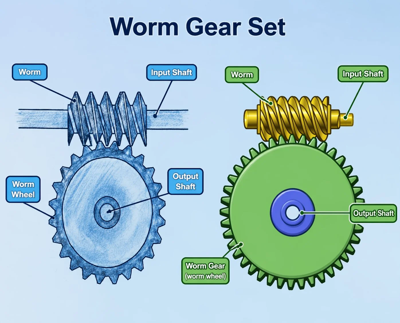
The two halves of every worm gear set
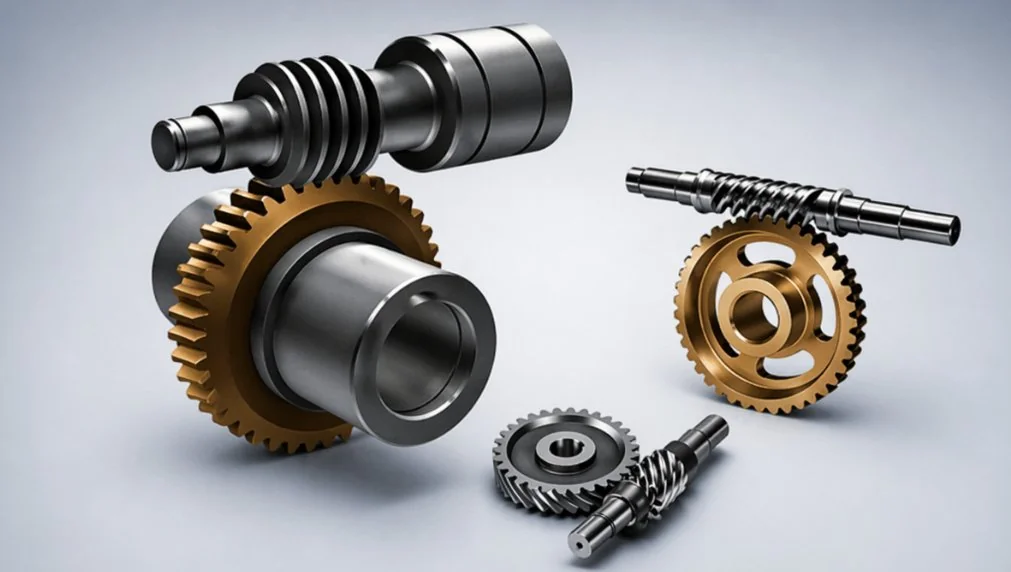
Whatever the catalogue size or end application, a worm and worm wheel system reduces to two engineered components. The worm — also called the worm shaft or drive screw — is a cylindrical shaft machined with one to four helical threads called starts. The worm wheel is the driven disc with oblique teeth that match the worm’s helix. The worm rotates; the wheel follows. That is the entire mechanism.
Specifying one without specifying the other is the most common mistake we see in first drawings from new customers. The two parts are matched as a pair, like a key and lock. A worm wheel cut for a 1-start worm cannot run smoothly against a 2-start worm of the same module, even though both look interchangeable on a parts shelf. When ordering replacement components, always quote both halves of the set together.
Worm shaft
The shaft sees high-pressure sliding contact, so it has to be hard enough to resist scuffing and wear. Standard practice across Korean and Japanese OEM programmes is case-hardened alloy steel — JIS SCM415, Chinese 20CrMnTi, or German 16MnCr5 — carburised to 58 to 62 HRC at the tooth flank. The core stays tougher (around 30 to 35 HRC) to absorb shock. After heat treatment the threads are ground on a profile grinder to bring tooth flank roughness below Ra 0.4 micrometers, because every micrometer of asperity adds friction in a sliding interface.
Worm wheel
The wheel is intentionally softer than the shaft, usually by a factor of about 2:1 in hardness. Bronze is the traditional choice — tin bronze (CuSn12) for general industrial drives, aluminium-iron bronze (CuAl10Fe5Ni5) for heavy duty. The softer bronze absorbs the sliding wear preferentially, which protects the more expensive hardened shaft. Over the life of the assembly you will replace the wheel once or twice while the worm shaft soldiers on. That is the whole point of the hardness mismatch: bronze is the sacrificial layer that keeps the steel safe.
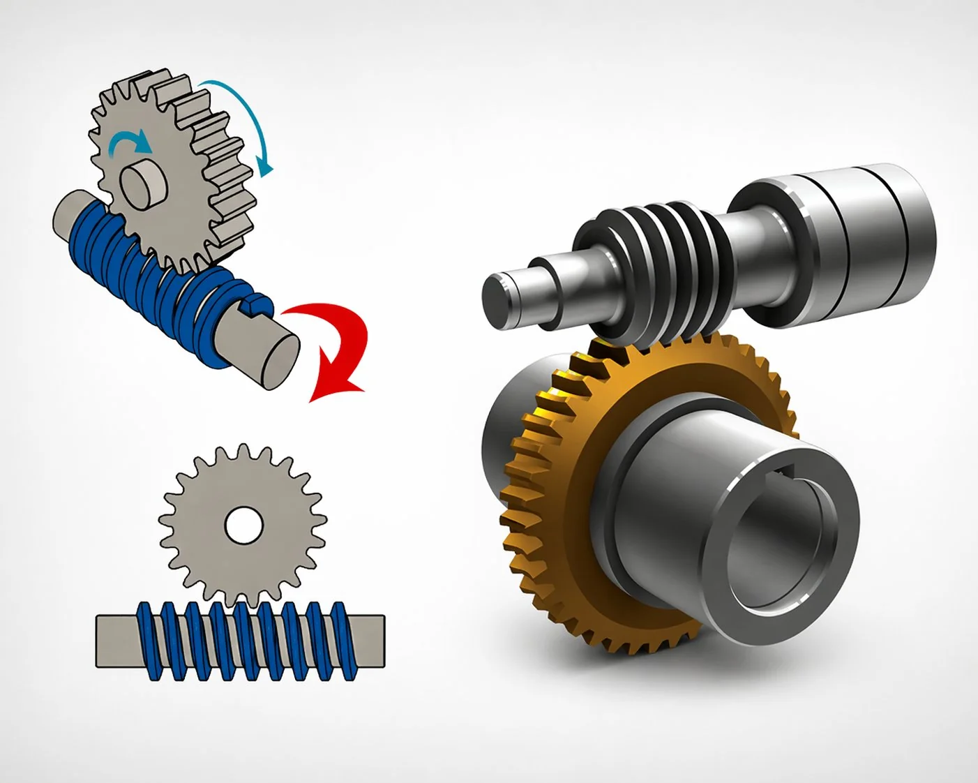
How the mechanism actually moves
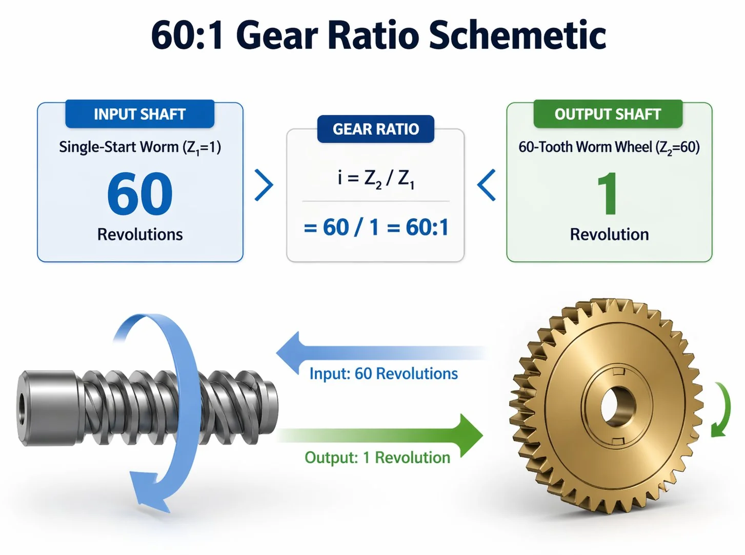
Picture a single-start worm spinning at 1,500 rpm. Each full rotation of the worm advances the wheel by exactly one tooth. If the wheel has 40 teeth, it rotates 1/40 of a turn per worm rotation, giving you 1,500 ÷ 40 = 37.5 rpm at the output. The reduction is 40:1, achieved in one stage, with the output shaft pointing 90 degrees away from the input.
A multi-start worm cuts that ratio proportionally. A 2-start worm on the same 40-tooth wheel gives 20:1, a 4-start worm gives 10:1. The fewer starts you specify, the higher the ratio per stage — but also the lower the efficiency, because the lead angle gets shallower and friction climbs.
The output torque scales roughly with the ratio minus friction losses. A 40:1 worm and worm wheel pair operating at 75 percent efficiency gives you 30 times the input torque at the output shaft — still a remarkable amplification for one component pair. For a deeper dive on the exact lead-angle formula and worked examples, see our companion article on worm gear ratio and calculation.
The defining trait: sliding contact, not rolling
In a spur or helical gear, teeth roll across each other with only a small sliding component near the pitch line. In a worm and worm wheel pair, contact is overwhelmingly sliding — the helix of the worm scrapes across the wheel tooth flank as it rotates. This single physical fact drives almost every other characteristic of worm gearing.
Sliding generates heat. A worm drive running at full load can warm the oil sump 30 to 50 degrees Celsius above ambient, which is far hotter than an equivalent helical reducer. Sliding wears the softer surface — that is why the bronze wheel is sacrificial. Sliding requires a thicker lubricant film than rolling contact does, which is why a generic hydraulic oil will destroy a worm gearbox in weeks. Sliding also damps vibration and produces almost no audible meshing noise, which is why these drives are the default choice in office equipment, medical devices, and packaging lines where quiet operation matters.
If you remember nothing else from this section, remember the sliding-versus-rolling distinction. Every conversation about a worm gearbox eventually traces back to it.
In two decades on the floor I have watched designers reach for a worm gearbox because they remembered “high reduction in small space” from school, then specify a hydraulic oil because that is what the rest of the machine uses. The drive runs five weeks before the bronze wheel teeth scuff into a smooth groove. Lubrication selection is not a finishing detail on a worm drive — it is half the engineering. ISO VG 460 or 680 with yellow-metal-safe additives is the right starting point for almost every application below 80 degrees Celsius sump temperature.
The self-locking property — feature, trap, and when to skip it
When the lead angle of the worm is below roughly 5 degrees, static friction at the tooth contact exceeds the force the wheel can apply back on the worm. The worm can drive the wheel forward, but the wheel cannot drive the worm backward. The drive holds position when input power is removed. This is the self-locking property that puts these drives inside hoists, valve actuators, antenna positioners, and elevator drives — all places where an unintended back-drive would be dangerous.
Self-locking is geometric, not absolute. Vibration can break it — a load that perfectly holds when stationary may slowly creep down under cyclic shock. Lubricant film thickness changes the friction coefficient, so the same drive may self-lock cold and back-drive when hot. For any application where a falling load would injure someone or damage equipment, treat self-locking as a useful auxiliary feature and specify a separate mechanical brake as the primary safety device. We have seen too many “self-locking” drives drift overnight because vibration from neighbouring machinery slowly walked the load down.
Some drives need to back-drive on purpose — clutch mechanisms, hand-cranked emergency overrides, or systems where the output must be free-wheeling when input power stops. Higher lead angles (above 12 degrees, achieved with 3-start or 4-start worms) eliminate self-locking and raise efficiency to 85–92 percent. The trade-off is no holding capability when the motor is off. Get this specification right at the design stage; converting between self-locking and back-drivable layouts after the housing is cast usually means a complete redesign.
Single-stage reduction capability — the headline feature
The compact ratio density of a worm and worm wheel pair is why this gearing has refused to be displaced by other technologies for two centuries. The table below shows what other parallel-shaft arrangements need to match what a single worm stage delivers.
Each additional stage in a competing technology adds shafts, bearings, housing length, oil volume, and weight. By the time a helical train reaches 60:1, it is twice the package size of an equivalent worm gearbox and costs more in materials despite higher unit efficiency. The crossover point where helical gearing becomes cheaper on total cost of ownership is roughly 10 horsepower at ratios above 20:1 — below that threshold, the worm and worm wheel set wins on capital cost almost every time.
When you should choose worm gearing — and when you should not
Honest selection guidance is more valuable than a feature list. The framework below is what our engineering desk uses on the first specification call with a new Korean OEM customer.
Choose a worm drive when
- You need ratios from 20:1 to 200:1 in a single compact stage.
- The output shaft must sit at 90 degrees to the input.
- Self-locking holding is desirable (lifts, hoists, parking brakes, valve actuators).
- The drive runs intermittently rather than continuously, so heat dissipation is not the binding constraint.
- Quiet operation matters and the duty cycle does not justify a full helical train.
- Total power is below roughly 10 kilowatts and unit cost is a critical procurement metric.
Choose something else when
- The drive operates 24 hours per day at peak load — sliding heat will reduce service life dramatically.
- Energy efficiency is a critical specification (electric vehicles, battery-powered tools, solar trackers where every percent counts).
- Power exceeds 15 kilowatts at moderate ratios — a helical right-angle gearbox usually wins on lifetime cost.
- The application requires positive back-drivability without a separate clutch.
- Maintenance access is impossible and design life exceeds 60,000 hours — bronze wheel wear becomes the limiting factor.
Materials worth knowing about
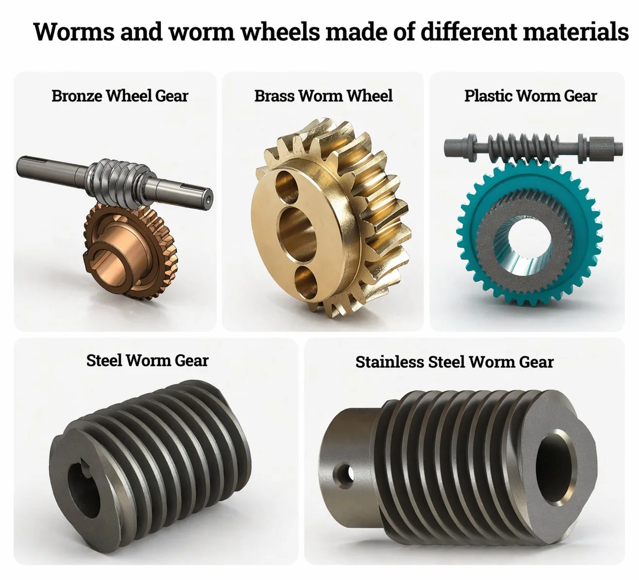
Five material pairs cover roughly 95 percent of orders we ship out of Ansan each quarter. The hardness ratio between shaft and wheel matters more than the absolute hardness of either component, and the right pair depends entirely on the operating environment.
Carbon-steel-on-tin-bronze is the workhorse for general industrial drives. Alloy-steel-on-aluminium-iron-bronze handles heavy hoists and 24/7 conveyors. Stainless-on-stainless covers food, pharmaceutical and marine duty. Cast-iron-on-40Cr-steel goes into low-speed cement and mining slurry drives. Plastic pairs (POM worm, PA66 wheel) live in micro-instrument applications where load is light and silence matters.
Where you actually find them in 2026
Worm gearing is more common in modern equipment than most engineers realise. The list below covers the high-volume use cases we see in our Korean and Japanese order book — but is not exhaustive.
If your application is not on this list, it does not mean a worm drive is wrong for you — it means we should look at the duty cycle and load profile together. Send the drawing to our engineering desk for a worm gear selection review and you will get a frank opinion in one Korean working day, including whether a different gear family would actually serve you better.
Misconceptions worth dispelling before you specify one
“Worm gearboxes are obsolete technology.” The geometry is centuries old, but the materials, surface finishes, and lubricants have advanced enormously. A modern unit built with ground SCM415 worm, AlFe bronze wheel and a yellow-metal-safe synthetic PAG oil runs at 90 percent efficiency in light-load conditions and lasts 40,000 hours. Calling that obsolete is like calling a hydraulic cylinder obsolete because Pascal’s law was published in 1647.
“Self-locking is automatic safety.” No. Self-locking is geometric and depends on lead angle, friction coefficient, lubricant film, and the absence of vibration. For any safety-critical lift, specify a separate mechanical brake and treat self-locking as a useful auxiliary.
“You can use any gear oil.” The lubricant for sliding contact is a specialty product. Standard hydraulic oil lacks the extreme-pressure additives needed. Some EP additives — particularly the active sulphur-phosphorus class — corrode bronze wheels at temperatures above 70 degrees Celsius. Always use an oil rated for this service and explicitly safe for yellow metals.
“More starts always means better.” More starts raise efficiency but cut the per-stage ratio. A 4-start unit on a 40-tooth wheel gives 10:1 at maybe 88 percent efficiency. A 1-start unit on the same wheel gives 40:1 at maybe 65 percent. There is no universal “best” — only the right number of starts for the specific ratio and efficiency target your application demands.
Like any engineered component, this device rewards careful specification and punishes shortcuts. Match shaft hardness to wheel hardness in the right ratio. Pick the lubricant before you finalise the housing geometry. Decide self-locking versus back-driving at the design stage, not after the prototype is built. Treat the bronze wheel as a wear part with a known service interval, not as a permanent fixture. Do those four things and a properly specified unit will outlast every other component in the drive train.
For Korean and Japanese OEM customers comparing catalogue options against a custom geometry quote, the full Ever-Power line of bronze and alloy steel worm gear sets covers Ø5 mm micro-modules through Ø300 mm industrial wheels. Drawings reviewed under NDA and quoted within one working day.
Frequently asked questions
Q: What is the difference between a worm gear and a worm wheel?
Strictly speaking the worm is the threaded driving shaft and the worm wheel is the toothed driven disc. In casual use, “worm gear” often refers to either component or to the complete pair. When ordering parts, always specify both halves of the set together — they are matched as a pair and not interchangeable across different module or start counts.
Q: Are worm gear and worm gearbox the same thing?
No. A worm gear (or worm gear set) is the bare component pair — worm shaft plus worm wheel. A worm gearbox or worm gear reducer is the complete sealed assembly that includes those components plus a housing, bearings, oil seals, and shaft extensions. Worm drive is a more general term that refers to the mechanism rather than a specific product format.
Q: Why is the worm wheel softer than the worm shaft?
Sliding contact preferentially wears the softer material. By making the wheel softer (typically bronze) than the worm (typically hardened steel), the wheel absorbs the wear over the assembly’s life, protecting the more expensive shaft. You will replace the wheel once or twice while the worm shaft remains serviceable. The hardness ratio is roughly 2:1 in standard practice.
Q: What is the typical efficiency of a worm gear set?
Efficiency depends heavily on the lead angle, lubrication, and load. A modern 10:1 multi-start worm gearbox can run at 88 to 92 percent efficient. A 60:1 single-start drive will typically operate at 55 to 70 percent. The relationship is geometric: shallower lead angles deliver higher ratios but lose more energy to sliding friction.
Q: How long does a worm gear last?
A properly dimensioned bronze worm wheel typically runs 20,000 to 40,000 operating hours before requiring replacement. Drives with synthetic oil and oversized wheels can extend this to 60,000 hours. The hardened worm shaft itself usually outlasts two or three wheel replacements when lubrication is adequate. Service life is most often limited by lubricant condition rather than tooth wear.
Q: Can a worm wheel drive the worm shaft?
In a self-locking layout (lead angle below about 5 degrees) — no, the wheel cannot back-drive the worm. In a non-self-locking layout (higher lead angle, multi-start worm) — yes, back-drive is possible and often used in clutches and emergency-release mechanisms. The geometry determines the answer; check the lead angle on the drawing if unsure.
Q: What lubricant should I use in a worm gearbox?
For most industrial drives, ISO VG 460 or 680 compounded mineral oil with yellow-metal-safe additives works as a default. Above 70 degrees Celsius sump temperature, switch to PAO synthetic. For high-efficiency applications, polyglycol (PAG) lubricants reduce friction and operating temperature significantly but are not compatible with mineral oil — full flushing is required when changing.
Got a worm gear application in mind?
Send a drawing or describe the duty cycle. Our engineering desk in Ansan will tell you whether a worm and worm wheel pair is genuinely the right fit, or whether something else would serve you better — even when the honest answer costs us the sale.
Editor: Cxm


