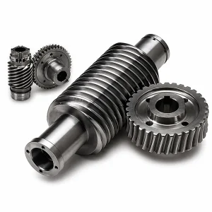
Custom Worm Gear Sets | Worm Drive

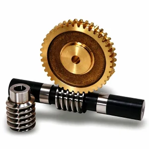
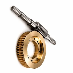
Customised worm gear sets in Brass, C45 steel, Stainless steel (304/316), Copper, POM, Aluminium, Alloy (20CrMnTi), cut to DIN 6 accuracy with 0.001 mm tolerance bands and 20-day sample turnaround, shipped from Korea to fit elevator, conveyor and machine-tool drive assemblies.
Overview of the Custom Worm Gear Sets
A worm gear shaft is the cylindrical drive element on which the worm thread is cut and through which input torque enters the gear set. It is the hardest-working piece in a worm transmission — every newton of output torque travels through this single part before reaching the mating wheel. Because of the continuous sliding contact at the thread flank, the shaft has to resist surface wear, axial thrust, and bending deflection at the same time, which is why material choice and heat treatment matter more here than on almost any other gear component.
Ever-Power produces both straight and tapered worm drive shafts from M1 through M12 in seven standard materials, ranging from C45 carbon steel for general-purpose drives up to 20CrMnTi case-hardened alloy for high-cycle machine-tool spindles. Korean customers working in elevator manufacture, steel-mill conveyors, machine tools, robotic arms and solar tracking systems use the catalogue as a drop-in replacement for existing proprietary shafts — we match bore diameter, lead angle, helix hand, and centre distance from a sample or a legacy drawing.
Technical Specifications of the Worm Drive Shaft
The specification envelope below covers the catalogue range. Dimensions, tolerance band and finish can all be tuned during order entry — send a stamped print or a clear photograph of the failed part, and the engineering desk produces a reverse-engineered drawing inside two working days for sign-off.
| Parameter | Specification |
|---|---|
| Model Number | M1, M2, M3, M4, M5, M8, M12 and others on request |
| Material | Brass, C45 steel, Stainless steel (304/316), Copper, POM, Aluminium, Alloy (20CrMnTi) |
| Surface Treatment | Zinc plating, Nickel plating, Passivation, Oxidation, Anodisation, Geomet, Dacromet, Black Oxide, Phosphatising, Powder Coating, Electrophoresis |
| Standard | ISO, DIN, ANSI, JIS, BS, Non-standard |
| Precision Grade | DIN 6 / DIN 7 / DIN 8 / DIN 9 |
| Teeth Treatment | Case-hardened (HRC 58–62 typical), milled, or ground |
| Tolerance | 0.001 mm / 0.01 mm / 0.1 mm (selectable) |
| Finish | Shot/sandblast, heat treatment, annealing, tempering, polishing, anodising, zinc plating |
| Packing | PE bag + carton, or wooden crate for bulk |
| Payment Terms | T/T, L/C |
| Production Lead Time | 20 business days for sample; 25 days for bulk |
| Sample Price | USD 2 – USD 100 (freight paid by client) |
| Typical Applications | Automation, semiconductor, general industry, medical, solar, machine tools, parking systems, rail and aviation ground equipment |
Worm Shaft vs Helical, Spur and Bevel Shafts
Engineers specifying a right-angle reduction often weigh a worm drive against helical, spur and bevel alternatives. Each geometry answers a different design question — the comparison below is what our Seoul technical desk uses when walking a customer through their first selection.
| Criterion | Worm Drive | Helical | Spur | Bevel |
|---|---|---|---|---|
| Max ratio per stage | 10:1 – 300:1 | typically 6:1 | typically 5:1 | typically 6:1 |
| Typical efficiency | 50 – 90 % | 95 – 98 % | 96 – 99 % | 94 – 97 % |
| Self-locking | Yes (low lead angle) | No | No | No |
| Running noise | Very low | Low | Moderate to high | Moderate |
| Shaft arrangement | 90° skew | Parallel | Parallel | 90° intersecting |
| Relative cost | Moderate | Higher | Low | Higher |
- ▸Choose a worm drive when the design needs a large reduction in one stage, self-locking behaviour, or a quiet 90° transmission.
- ▸Choose helical when efficiency is the priority and the shafts are parallel.
- ▸Choose spur when cost and simplicity outrank noise concerns — common in hand-cranked mechanisms.
- ▸Choose bevel when shafts intersect at 90° and high efficiency is required at a moderate ratio.

Non-Throat, Single-Throat and Double-Throat Gears
The thread-cutting geometry on the shaft itself determines which family the finished worm drive belongs to. The three families carry different load ratings and different cost profiles.
◉Non-throat worm shaft — the thread is cut on a straight cylindrical blank. Tooth contact between the shaft and the wheel is essentially a point, which limits continuous load rating. This is the most common and lowest-cost geometry, used in catalogue replacement shafts up to around M3.
◉Single-throat worm shaft — the wheel is cut with a concave face so it partly wraps the cylindrical shaft, producing line contact. The shaft itself is still straight. This is the workhorse of industrial gear drives and the default specification from M3 upward.
◉Double-throat (globoidal) worm shaft — the thread is cut on a concave hourglass-shaped blank, and the wheel is equally concave. Both parts wrap each other, giving conjugate line contact along several teeth simultaneously. Load capacity goes up roughly 2× compared with single-throat, at 20 – 30 % higher unit cost and longer manufacturing lead time.


Materials and Heat Treatment for the Worm Gear
Because the worm slides against its mating wheel — not rolls — tooth-flank wear is the dominant failure mode. The goal of heat treatment is simple: a hard, wear-resistant surface over a tough, ductile core that absorbs shock without cracking. The material matrix below is what we quote against roughly 95 % of shaft enquiries.
- ⬢C45 carbon steel, induction-hardened. Threads reach HRC 50 – 55 at the flank with a ductile core. The default choice for M3 – M8 general-purpose worm drive shafts.
- ⬢20CrMnTi case-hardened alloy. Carburised to 0.8 mm case depth and quenched to HRC 58 – 62. The specification for machine-tool spindles, heavy hoists and 24/7 conveyor drives.
- ⬢40Cr / 42CrMo4. Through-hardened alloy steel for impact-loaded drives in mining and crushing equipment.
- ⬢Stainless steel 304 / 316. Specified for food, pharmaceutical and marine environments where corrosion resistance outranks absolute hardness.
- ⬢Brass and aluminium alloy. Low-load, corrosion-sensitive applications such as valve actuators and instrument drives.
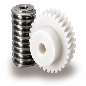
- ⬢POM (Polyacetal). Non-metallic option for light-duty, low-torque drives where noise and self-lubrication are priorities.
Thread-grinding after heat treatment is available on all hardened shafts and is mandatory for DIN 6 accuracy. The ground flank finish — below Ra 0.4 µm — also extends service life by cutting sliding friction at the contact zone.
Selection Guide: Getting the Shaft Spec Right
A worm drive shaft is not a stand-alone part; it has to match the wheel, the housing and the application envelope. The seven inputs below are what the design desk needs before quoting.
- ➤Module and pressure angle — must match the worm wheel exactly. Standard values are M1, M2, M3, M4, M5, M8, M12.
- ➤Number of thread starts and lead angle — sets the reduction ratio and whether the drive is self-locking. Single-start shafts below 5° lead angle are self-locking.
- ➤Helix hand — right or left. Has to match the wheel; swapping hands will reverse output rotation.
- ➤Shaft diameters and bearing journals — input shaft extension, pilot diameter, bearing fit bands, keyway or spline detail.
- ➤Centre distance — controls the backlash at the tooth mesh. A 0.05 mm error can double the backlash on an M5 set.
- ➤Operating environment — temperature, humidity, wash-down, food contact. Drives sanitary-environment material choice.
- ➤Expected service life and duty cycle — 5 000 hours of 24/7 duty is a completely different specification from 50 000 cycles per year of intermittent operation.

Quality System, Certifications and Service Commitment
Every finished shaft leaves the factory with a batch inspection report that cross-references the drawing's critical dimensions. Korean tier-1 customers who require full PPAP documentation can have the package included with no extra charge — lead time extends by roughly five working days.
- ✓ISO 9001:2015 certified quality management system, annually audited by SGS.
- ✓CE marking for shafts supplied as part of completed drive assemblies into the European market.
- ✓RoHS and REACH compliance on all metallic finishes; material certificates of conformance (3.1) supplied on request.
- ✓In-house Gleason gear tester, Mitutoyo CMM and Leitz coordinate measuring equipment for dimensional verification.
- ✓24-month warranty against manufacturing defects, counted from shipment date at Korea Ever-Power Worm Gear Co., Ltd.
- ✓Korean-language technical documentation pack available for submission to KFDA, KATS or customs inspectors.
Companion Products for the Worm Shaft
Korean customers rarely buy the shaft alone. Most orders ship together with a matched bronze or aluminium-bronze wheel, axial-thrust tapered roller bearings, FKM oil seals and a retaining-ring package. For buyers who want the complete drive rather than loose components, a packaged worm gear reducer arrives pre-assembled, oil-filled, and ready to bolt to the driven machinery.
When the drive needs an integral electric motor and a specific output flange, the gearmotor-format worm gearbox is the usual choice. The full worm gear components catalogue shows every matched shaft-and-wheel pair we hold in tooling.

Frequently Asked Questions
Q: What determines the efficiency of a worm gear drive?
Three factors dominate: the lead angle of the worm (bigger angle means higher efficiency), the coefficient of friction at the thread flank (a ground surface with synthetic oil can halve friction compared with a milled one), and the reduction ratio (efficiency drops as ratio climbs). A typical 20:1 drive with a ground C45 shaft reaches 82 – 88 %; the same geometry at 80:1 sits closer to 65 %.
Q: Why is a worm drive self-locking, and how reliable is the self-lock?
When the lead angle is smaller than the equivalent friction angle between the thread flank and the wheel face, the wheel cannot back-drive the worm. For a greased steel-on-bronze interface the friction angle is roughly 5 – 6°, so single-start worms with a lead under 4° are reliably self-locking. The feature is still considered a safety-assist rather than a primary brake — always specify a mechanical brake for lift and hoist applications above 500 kg.
Q: Can you cut a fully custom, non-catalogue centre distance?
Yes. Custom centre distance, thread starts, helix hand and shaft-extension detail are all handled from a stamped drawing. MOQ on a first custom run is 20 pieces; repeats can drop to 5 pieces once tooling exists. Lead time stays at the standard 25 business days for most geometries.
Q: Do you reverse-engineer damaged shafts?
Routinely. Send the damaged part to our Seoul office or ship directly to Qingdao; we measure on a Mitutoyo CMM and produce a fully dimensioned CAD drawing in two working days. The drawing is returned for customer sign-off before any machining starts.
Q: What is the difference between an induction-hardened and a case-hardened worm shaft?
Induction hardening heats the surface locally with a coil and quenches rapidly, producing a 1 – 3 mm hardened zone at HRC 50 – 55. Case hardening (carburising) adds carbon to the near-surface layer at 900 °C over several hours, then quenches to HRC 58 – 62 with a deeper 0.8 – 1.5 mm case. Case hardening gives higher wear resistance and is preferred for 24/7 industrial duty; induction is faster, cheaper and adequate for moderate-duty drives.
Q: How do I know whether my shaft needs grinding after heat treatment?
If the specification calls for DIN 6 or DIN 7 accuracy, or if the drive runs above 1 500 rpm, grinding is mandatory — heat treatment always introduces small distortions that milling alone cannot remove. For DIN 8 and DIN 9 drives running below 1 000 rpm, milled-then-induction-hardened shafts perform well enough.
Q: Can the worm shaft be supplied with the worm wheel already assembled?
Yes. Matched assemblies with the mesh pattern already run-in on our test rig are available on request. This cuts on-site installation time and removes the risk of incorrect centre-distance shimming during first assembly.
Q: What lubricant works best for a hardened steel worm on a bronze wheel?
PAO-based synthetic gear oil in ISO VG 220 or VG 320 is the industry benchmark for continuous duty. Mineral EP oils work for intermittent duty but need more frequent change intervals. For food-contact applications, an NSF H1 synthetic oil is the right choice; for cold-start duty below −10 °C, step down to VG 150.
Customer Feedback
Bae Hyun-seok, Elevator Maintenance Chief, Daegu (late 2025)
"We maintain about 180 passenger elevators across Daegu and needed replacement worm shafts for three 1998-vintage units whose original manufacturer disappeared. Sent Ever-Power photos and the old service manual. They reverse-engineered the shaft in 48 hours, confirmed the drawing with our technician over video call, and shipped three finished shafts in 22 days. All three installed without modification and have been running smoothly for eight months."
Choi Seo-yeon, R&D Engineer, Suwon (early 2026)
"We were prototyping a new semiconductor wafer-transfer arm and needed five M2 ground worm shafts with a non-standard 27 mm centre distance. MOQ of 20 pieces from most suppliers killed the budget. Ever-Power machined exactly five, charged a fair NRE, and delivered in 18 days. Prototype passed functional testing on first assembly. The willingness to do small runs was the deciding factor."
Park Ji-hoon, Production Supervisor, Changwon (mid 2025)
"Replaced a failed shaft on our steel-mill coil-handling drive. The original part was a 20CrMnTi case-hardened shaft we had been buying from a European supplier at high cost. Ever-Power matched the spec including the 0.8 mm case depth and delivered at roughly 45 % of the original price. Been running six months, no measurable wear on the tooth flank so far."
Yoon Ha-eun, Machine Tool Designer, Busan (late 2024)
"Small detail that mattered: their engineer caught a mistake in my drawing — I had specified RH helix on a shaft that needed to match an LH wheel. Took the time to email me instead of just cutting it wrong. Saved me an expensive rework. Been sourcing from them for eighteen months since."
Tran Thi Mai, Packaging Line Manager, Ho Chi Minh City (early 2025)
"Stainless steel worm shaft for our beverage filling line. Food-contact documentation arrived with the shipment, not two weeks later after chasing. Installation was straightforward. Running temperature around 52 °C oil-sump, well inside spec. Would buy again."
Jung Soo-ah, Robotics Integrator, Seongnam (mid 2025)
"Specified M3 ground worm shafts for a six-axis palletising robot. DIN 6 accuracy, ground after case hardening. Backlash measured on final assembly was 18 arc-seconds — tighter than the original Japanese part we replaced. The Korean-speaking engineer in Seoul walked us through the run-in procedure, which helped the robot pass end-user commissioning on first try."
Additional information
| Editor | Cxm |
|---|
Related products
-
Alloy Steel Worm and Worm Gear for Auto Parts | Ø5-Ø120 Module 0.2-2.2
-
Stainless Steel Worm Gear for CNC Machinery | DIN 5 SCM415
-
Duplex Worm Gear Set | Dual-Lead Zero-Backlash Worm Drive
-
Cylindrical Worm Wheel Sets | Line-Contact Worm Gearing
-
Brass Worm Wheel & Shaft Set | 20-Tooth M0.5 Micro Gear Kit
-
Worm and Wheel Sets | DIN6 Worm Gearing
-
Plastic Worm Gears for Micro Drives | POM & Nylon Gear Sets


