Duplex Worm Gear Set | Dual-Lead Zero-Backlash Worm Drive
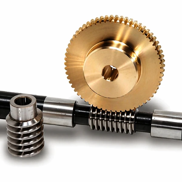
Dual-lead duplex worm gear sets with zero-backlash adjustment down to ±0.045 mm, built for indexing tables, CNC milling spindles and precision presses where reversing accuracy must survive tens of thousands of cycles.
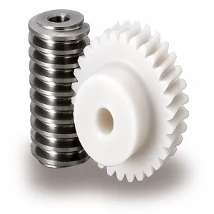
Duplex Worm Gear — What Makes It Different
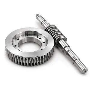
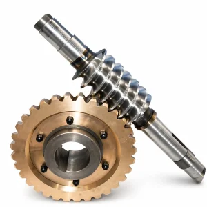
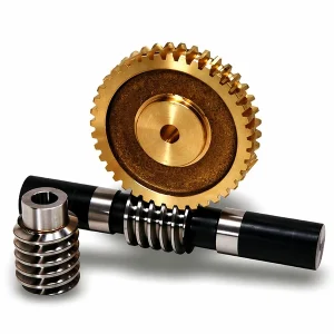
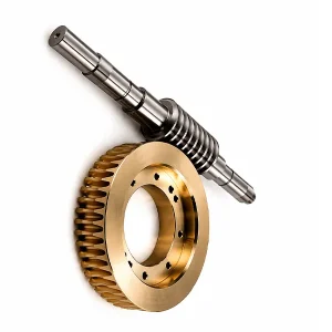
A duplex worm gear — also called a dual-lead worm — is a specialised variant in which the two flanks of the same worm thread are cut with slightly different modules and slightly different diameter quotients. The effect is subtle on the shop floor but decisive in the field: the tooth thickness grows steadily from one end of the worm to the other, while the gap between adjacent threads shrinks at the same rate. Shifting the worm axially inside the gearbox moves a thicker or thinner section of thread into mesh, which means backlash can be dialled in to any target value at assembly — and re-dialled later in life as the drive wears.
On the wheel side the picture mirrors the shaft. Different modules on the two flanks produce different addendum modification coefficients and different rolling-circle diameters, so the front and rear tooth profiles of the wheel are not identical, even though the tooth thickness and tooth gap stay constant around the wheel's circumference. The outcome is a drive that delivers single-digit-micrometre backlash when needed, and holds it through reversing service that would quickly wear out a conventional worm set. Korean machine-tool builders, rotary-indexing specialists and stamping-press manufacturers are the most frequent buyers.
Technical Specifications
The values below reflect the standard catalogue envelope for duplex sets. All geometry is cut to customer drawing — duplex worms are almost never stock items because the lead-difference value itself is an application-specific parameter. Values marked "typical range" reflect industry-standard practice where the customer has not yet specified a tighter target.
| Parameter | Specification |
|---|---|
| Worm Type | Dual-lead (different modules on left and right flank) |
| Backlash Range | ± 0.045 mm at reference tooth (adjustable down from larger values) |
| Module Range | M1 – M10 (typical range) |
| Typical Lead Difference | 0.05 – 0.20 mm per turn (typical range, tailored per drawing) |
| Worm Material | 20CrMnTi case-hardened (HRC 58 – 62) or 40Cr through-hardened |
| Wheel Material | Tin bronze (CuSn10), aluminium-iron bronze (CuAl10Fe3) |
| Tooth Finish | Ground after heat treatment (mandatory for duplex) |
| Precision Grade | DIN 5 – DIN 6 (standard for duplex sets) |
| Reference Marking | V-groove (60°, 0.3 mm deep) on tip of reference tooth |
| Assembly Orientation | Arrow mark stamped on both worm and wheel |
| Lead Time | 25 – 35 business days (longer for DIN 5) |
| Primary Applications | Rotary and tilting tables, CNC milling machines, presses, indexing drives |
How the Backlash Adjustment Actually Works
Backlash on a conventional drive comes from the clearance between the mating tooth flanks at the pitch line. On a duplex set, that clearance is no longer constant along the shaft — it changes linearly from one end to the other, because the tooth thickness itself changes linearly. Shifting the shaft 1 mm axially can move backlash by 20 – 40 µm on a typical M4 set, depending on the lead difference specified during design.
Adjustment on assembly is a four-step process. First, the shaft is fitted to the housing with a packer or spacer set that allows a ±2 mm axial shift. Second, the wheel is rotated by hand while the installer feels for backlash at the output shaft. Third, the shaft is shifted axially toward the thicker-tooth end until the desired backlash is reached. Fourth, the packer set is finalised and the lock nut torqued. Re-adjusting years later, after the drive has worn, follows the same steps but typically needs only 0.5 – 1.5 mm of additional shift.

Duplex vs Other Backlash-Control Methods
Several workshop-level methods exist to reduce worm-gear backlash. Each one works, but each carries a penalty the duplex method avoids. Understanding the trade-offs is the reason design engineers specifying precision indexers pay the duplex premium willingly.
| Method | How It Works | Main Drawback |
|---|---|---|
| Eccentric hub rotation | Rotate the hub that cradles worm and wheel, changing centre distance | Shifts tooth contact zone, distorts contact pattern, degrades load rating |
| Conical worm axial shift | Move a tapered worm along its axis into a matching wheel | Interferes with geometrically correct meshing, high start-up wear |
| Split worm (Ott system) | Two worm halves rotated or shifted relative to each other | Complex assembly, risk of improper alignment, reduced efficiency |
| Split wheel (two-disc) | Two wheel halves rotated close to each other to preload the worm | Higher friction, heat rise, and wear at the preloaded contact |
| Duplex (dual lead) | Axially shift the dual-lead worm to select tooth thickness at mesh | Higher manufacturing cost; no geometric or wear penalty |
The bottom row is the only one that preserves geometrically accurate meshing after adjustment. Contact area, load capacity and efficiency are left untouched — the drive works exactly as it did before the adjustment, just at a different backlash value. That property is why duplex sets dominate the precision-indexing market despite costing 40 – 60 % more than equivalent standard worm sets.
Assembly Orientation and Reference Tooth Check
Because the worm and wheel have different thickness profiles on the two flanks, a duplex set is not symmetrical — it has a correct and an incorrect orientation. Ignoring this during installation causes the centre distance to sit larger than the design value, and the assembly becomes difficult or impossible to mount properly. Two pre-flight checks cover the common mistakes.
Check One — Orientation Arrows
▶ Both the shaft and the wheel are stamped with a small arrow at the manufacturer's assembly mark. When fitting the pair into the housing, rotate the wheel until the arrow faces the front, then feed the shaft into engagement so that its arrow points the same direction. If the arrows point opposite, the thicker tooth is meeting the thinner tooth of the wheel and the drive will bind before it reaches the design centre distance.
Check Two — Reference Tooth V-Groove
▶ The tip of the duplex shaft carries a 60-degree V-groove cut 0.3 mm deep — this is the reference tooth. When the reference tooth sits exactly aligned with the rotational centre of the wheel and the centre distance is set to the drawing value "a", the backlash sits at the design target (typically ± 0.045 mm for our catalogue frames). From that starting point, axial shift is used to tune backlash up or down as the application demands.

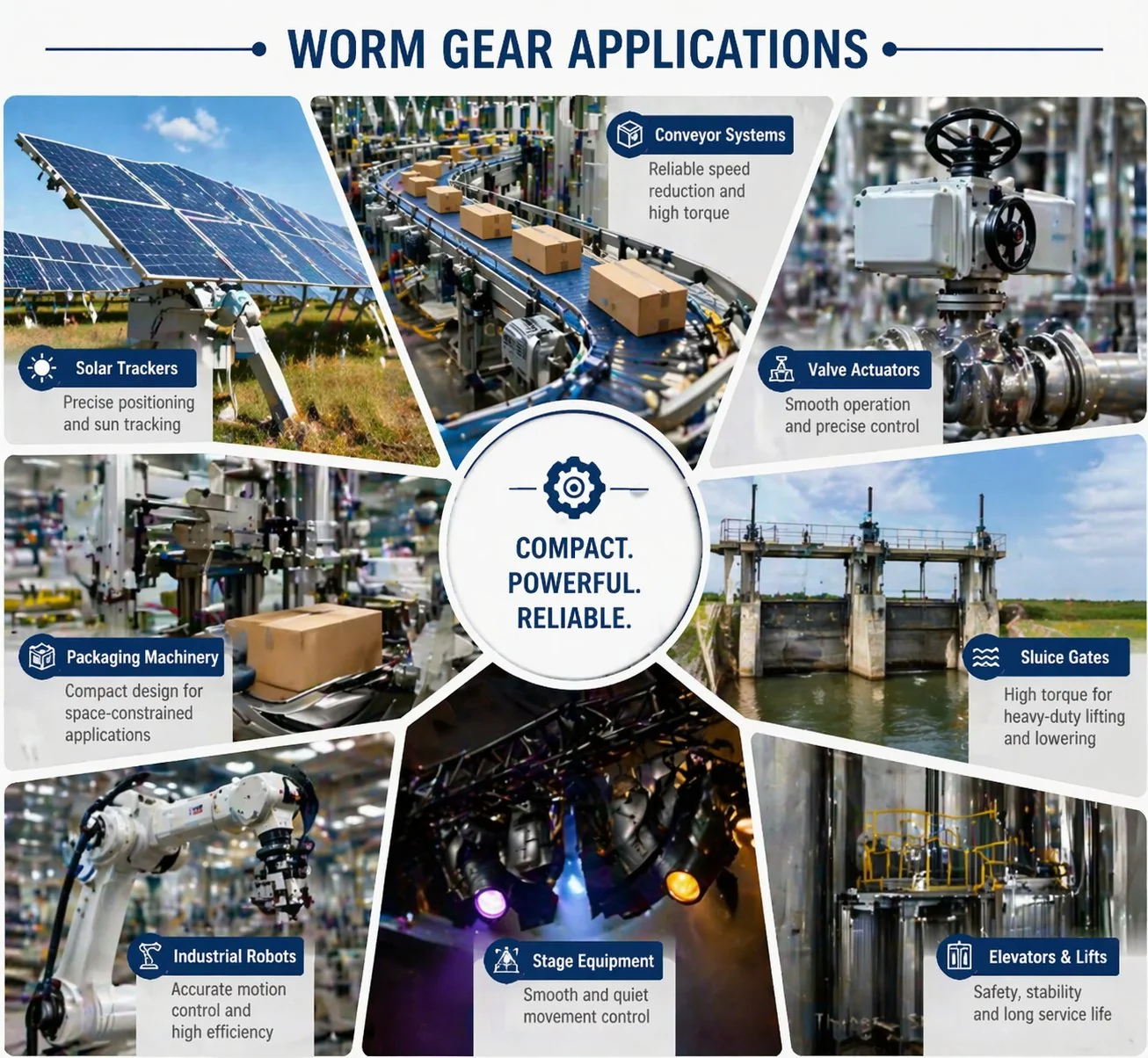
Typical Applications for Duplex Worm Gears
Duplex sets earn their extra cost in drives where reversing accuracy must survive tens of thousands of cycles without manual re-shimming. Korean industry uses them in several distinct application niches.
- ◆Rotary and tilting indexing tables. A duplex set holding 0.05 mm backlash delivers sub-arc-minute repeatability on a 300 mm-diameter table. Common in multi-axis machining centres built in Changwon and Masan.
- ◆CNC milling and boring machines. The worm axis on a rotary table inside a 5-axis mill sees continuous reversing loads. Duplex backlash control keeps the last few arc-seconds of positioning error inside the drawing tolerance even after 20 000 hours of service.
- ◆Mechanical presses with position-feedback control. Automotive body-panel presses and stamping lines need tight, repeatable ram positioning. A duplex drive on the flywheel coupling holds the position window.
- ◆Shock-protected reversing drives. When the downstream load slams back against the drive (as in some winding machines), duplex adjustment prevents the impact-induced backlash widening that degrades other worm drives.
- ◆Precision antenna and radar positioning. Pointing accuracy for Korean defence and telecommunications ground stations specifies duplex sets because of the repeatable reverse-direction performance.
Benefits Over Standard Worm Drives
Beyond the headline backlash advantage, a duplex set carries several less obvious benefits that matter to design engineers after the first few weeks of service.
- ✦Geometrically accurate teeth contact at every adjustment. Unlike eccentric or split-worm methods, duplex adjustment leaves the contact pattern unchanged.
- ✦Very fine backlash resolution. A 10 µm movement on the worm produces roughly a 1 – 2 µm change in backlash on a typical M4 set.
- ✦Insensitivity to minor centre-distance drift. Because duplex teeth are cut to involute profiles, small housing deflections from shaft loads do not cause meshing interference.
- ✦Re-adjustment across the service life. The drive can be tuned back to near-zero backlash several times without replacing parts, extending useful life by roughly 50 – 100 %.
- ✦Full load-carrying capacity. Adjustment never preloads the teeth, so the drive carries the rated torque at the rated efficiency even after many years.
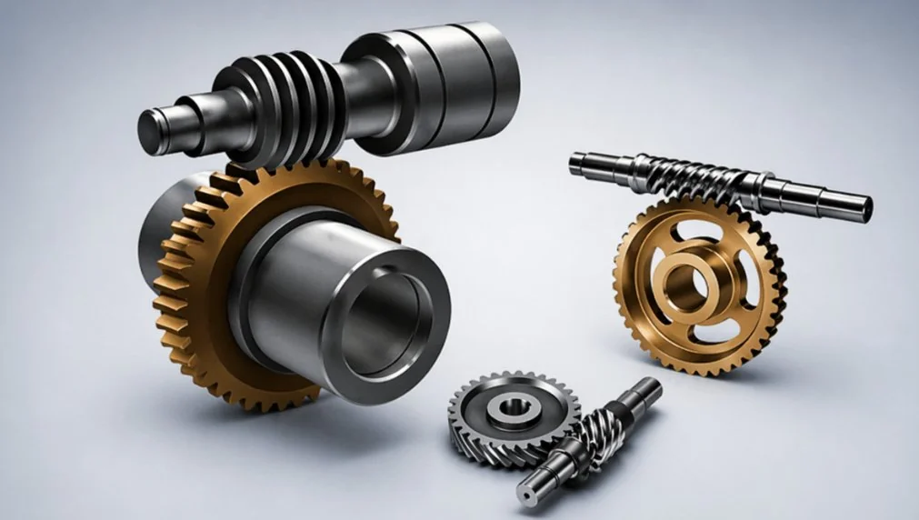
Companion Products for Duplex Drives
A duplex worm set is rarely supplied alone. Korean machine-tool builders commonly order matched axial-thrust bearings, FKM oil seals and a CNC-machined housing with shim packs included. For smaller OEMs without housing capacity in-house, the complete assembly can be delivered inside a packaged worm gear reducer already adjusted, run-in, and tagged with its measured backlash value.
When the drive has to include a servo motor for closed-loop positioning, the worm gearbox family can accept direct flange-mount motors in NEMA or IEC sizes. The full worm gear products catalogue covers every matched duplex pair from centre distance 40 mm up to 250 mm.

Frequently Asked Questions
Q: What tolerance does the duplex backlash adjustment actually reach?
With proper initial setup and a DIN 5 or DIN 6 set, the final backlash window sits around ± 0.045 mm at the reference tooth on a typical M4 assembly. Skilled installers achieve ± 0.020 mm on smaller modules. Below that, temperature drift and shaft deflection become the limits rather than the gear geometry.
Q: How often does the drive need re-adjustment during its service life?
Typical interval is every 8 000 – 12 000 operating hours for indexing drives with tight backlash requirements. Drives carrying lighter loads can run 20 000 hours between adjustments. When noise increases or positioning error starts to climb, it is usually time for a shift.
Q: Can you supply a duplex set to a customer drawing with a specific lead-difference value?
Yes. The lead-difference value is one of the core design parameters of a duplex worm and should be specified on the drawing. If the customer does not have a preferred value, our engineering team will recommend one based on the required backlash-adjustment range and the expected service life.
Q: What happens if the worm is installed in the wrong orientation?
The centre distance appears larger than the drawing value, and the drive binds before the worm reaches the housing bore's axial travel limit. If you try to force the assembly, tooth damage is likely within the first few revolutions. Always check the arrow marks before tightening any bolts.
Q: Does duplex geometry change the drive efficiency compared with a standard worm set?
No meaningful change. Because duplex adjustment works by selecting a section of thread rather than by preloading the teeth, the running efficiency matches the underlying worm-and-wheel geometry. Typical values are 82 – 88 % at 20:1, the same as a standard set of equivalent module and accuracy.
Q: What lubrication requirements apply to a duplex set?
Synthetic PAO gear oil in ISO VG 220 or VG 320 is the industry standard. Because duplex teeth have a slightly different contact geometry on the two flanks, sticking with a high-film-strength synthetic oil is especially important. Mineral EP oils work but need more frequent changes.
Q: Can the duplex worm be reverse-engineered from a failed sample?
Yes — the Mitutoyo CMM in our Korean-language-supported metrology lab can capture the dual-lead profile from a sample worm. Lead time for a reverse-engineered duplex set is typically 30 – 40 business days because the grinding setup for each flank has to be calculated from the measurement data.
Q: What is the MOQ for a custom duplex set?
Five pieces for a first production run, which lets a machine-tool builder build one prototype plus four production units. Repeat orders can drop to two pieces because the grinding setup is already captured in our CNC program.
Voice of the Customer
Kim Min-jae, Machine Tool Builder, Changwon (mid 2025)
"Specified duplex sets for the rotary table on a new 5-axis machining centre. Target backlash was 0.05 mm. On first assembly, after the recommended axial shift procedure, we measured 0.042 mm — right inside target. Three machines shipped to end customers so far, positioning accuracy on the final product certification exceeded specification on all three."
Choi Seo-yeon, Precision Indexing OEM Owner, Seongnam (late 2025)
"We build rotary indexers for semiconductor wafer-handling. Duplex from Ever-Power replaced a European brand we had been using for ten years. Accuracy matches, lead time is 40 % shorter, unit price is 55 % lower. The engineering drawings they returned before machining caught a mistake in our original spec — saved us from ordering an unusable part."
Nguyen Van Hung, Stamping Press Engineer, Hanoi (early 2025)
"We retrofit older mechanical presses for automotive body panels. Added a duplex-driven ram-position servo to three machines. The 0.05 mm repeatability on the duplex set made the feedback loop stable where a standard worm drive had been oscillating. Sixteen months of production, no measurable backlash increase so far."
Park Ji-hoon, Antenna Positioning Engineer, Daejeon (mid 2025)
"Ordered a duplex M3 set for a satellite ground-station azimuth drive. Pointing requirement was under 0.01 degree across 360 degrees of travel. After installation and the first backlash adjustment, we measured 0.007 degree RMS pointing error, well inside the contract tolerance. The Korean-language documentation was useful for the acceptance test in front of the customer."
Sakura Ito, Robotics Integrator, Osaka (late 2024)
"Used duplex sets in a custom pick-and-place robot for a medical-device assembly line. Backlash at the wrist axis had to be under 0.03 mm and had to stay there for at least 10 000 cycles of qualification testing. Ever-Power delivered two sets on a 28-day lead time, and both units passed qualification without intermediate adjustment."
Lee Jun-ho, Rotary Table Refurbisher, Ulsan (early 2026)
"Refurbished a 25-year-old Japanese-built rotary indexing table for a forging die-sinking job. Original duplex set had worn out; Ever-Power reverse-engineered from the failed worm, delivered in 32 days. Table now indexes to within 8 arc-seconds, which is actually tighter than the machine's original specification. Seoul technical support walked us through the break-in adjustment over video call."
Additional information
| Editor | Cxm |
|---|
Related products
-
Alloy Steel Worm and Worm Gear for Auto Parts | Ø5-Ø120 Module 0.2-2.2
-
Stainless Steel Worm Gear for CNC Machinery | DIN 5 SCM415
-
Cylindrical Worm Wheel Sets | Line-Contact Worm Gearing
-
Brass Worm Wheel & Shaft Set | 20-Tooth M0.5 Micro Gear Kit
-
Custom Worm Gear Sets | Worm Drive
-
Worm and Wheel Sets | DIN6 Worm Gearing
-
Plastic Worm Gears for Micro Drives | POM & Nylon Gear Sets


