Cylindrical Worm Wheel Sets | Line-Contact Worm Gearing
Line-contact cylindrical worm wheel and matched worm mill assemblies carrying worm peripheral speeds up to 10 m/s, engineered for industrial reduction drives where higher tooth force and quieter running outperform helical alternatives.
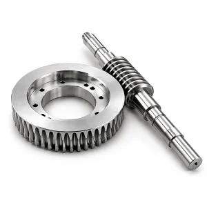
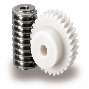
Cylindrical Worm Wheel — Product Overview
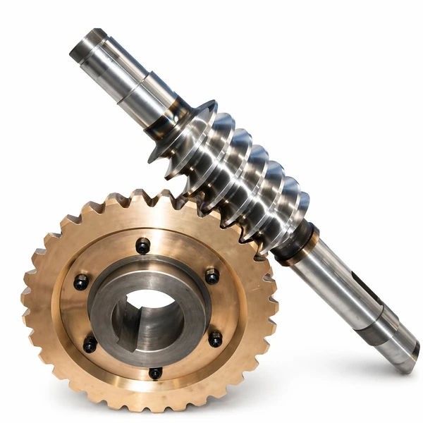
A cylindrical worm wheel is a wheel whose teeth have been milled by a cutter ground to the same basic geometry as the mating shaft. This production method is what distinguishes the two major families inside the cylindrical worm family: the "worm and helical gear" pair, where a small-tooth helical pinion meshes at a crossed-shaft angle and contacts the wheel at a single point; and the "worm and worm wheel" pair, where the teeth are cut with the same mill as the shaft thread, producing line contact along the engaged tooth flank. Line contact is why the second arrangement carries significantly higher tooth force before surface fatigue becomes the limit.
Ever-Power supplies both arrangements, but around 90 % of Korean industrial orders specify the true worm-and-worm-wheel pair because the extra load rating usually outweighs the modest cost difference. The product ships as a matched set — shaft plus wheel, cut from the same tool setup so the tooth profiles sit in perfect conjugate contact from the first revolution. Typical applications include conveyor drives, packaging-line indexers, solar tracker gearboxes, and parking-system lifts.
Technical Specifications
The specification envelope below covers the catalogue geometry. Module, centre distance and tooth count are the parameters most often customised from the base catalogue — send a stamped drawing or the mating wheel for measurement, and the engineering desk quotes against it within two working days.
| Parameter | Specification |
|---|---|
| Arrangement Type | Cylindrical worm-and-worm-wheel (line contact) or worm-and-helical-gear (point contact) |
| Module Range | M1 – M12 (typical range) |
| Wheel Material | Aluminium-iron bronze (primary) / tin bronze / ductile cast iron (low-speed only) |
| Worm Material | C45 steel / 20CrMnTi case-hardened alloy / stainless steel |
| Worm Peripheral Speed | Up to 10 m/s (below this, standard oil bath is sufficient) |
| Precision Grade | DIN 6 / DIN 7 / DIN 8 / DIN 9 |
| Teeth Treatment | Hobbed, hardened, milled or ground |
| Contact Geometry | Line contact on worm-mill-cut wheels (preferred) |
| Lubrication | Oil bath up to 10 m/s; splash ring or forced feed above |
| Typical Ratio Range | 10:1 – 100:1 in a single stage |
| Lead Time | 20 days for sample; 25 days for bulk |
| Standard Compliance | ISO 1122, DIN 3974, JIS B 1723 (typical range) |
Values noted "typical range" reflect the standard catalogue envelope; non-standard modules, speeds or ratios are supplied to customer drawing after a short engineering review.
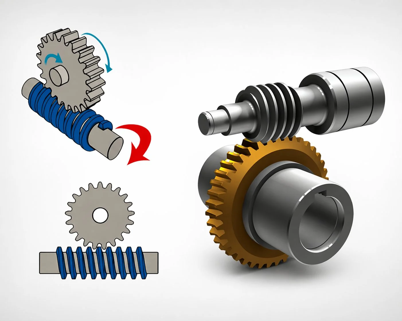
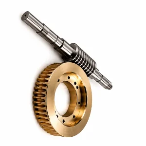
How the Cylindrical Worm Drive Transmits Power
The cylindrical arrangement works because the worm thread and the wheel teeth have been cut from the same basic geometry. When the shaft rotates, its thread flank slides against the wheel tooth flank along a contact line that sweeps across the tooth face once per revolution. The continuous sliding is why these drives need thicker, higher-pressure oil than gear drives and why efficiency sits lower — energy lost to sliding friction shows up as heat in the oil sump.
Two production choices decide the mesh quality. The first is whether the wheel is milled with a true dedicated mill (the preferred method, giving line contact) or with a standard helical hob (cheaper, but producing only point contact). The second is whether the shaft thread is ground after heat treatment to remove distortion — a step that becomes mandatory once the specification calls for DIN 7 or tighter. On high-speed drives where the shaft peripheral velocity exceeds 10 m/s, oil-bath lubrication starts to fail because the thread cannot pick up enough oil from the sump; at that point the wheel moves above the shaft (so-called overhead arrangement) and a splash ring is added to deliver oil to the bearings. This single change buys an extra 3 – 5 m/s of usable peripheral speed.
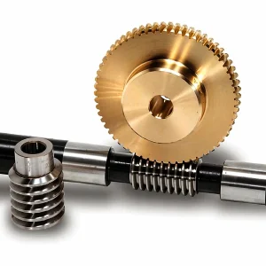
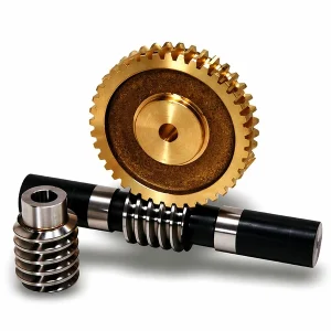
Bronze Grades and Cast Iron — Wheel Material Matrix
Material choice on the wheel side drives almost every long-term characteristic of the drive: wear rate, efficiency, temperature stability, and unit cost. The table below summarises the three grades we stock, with the honest trade-offs for each.
| Wheel Material | Anti-Galling | Strength | Cost | Best Fit |
|---|---|---|---|---|
| Tin bronze (CuSn10) | Excellent | Moderate | High | Continuous-duty drives, heat-sensitive applications |
| Aluminium-iron bronze (CuAl10Fe3) | Good | High | Moderate | Impact-loaded drives, larger modules |
| Ductile cast iron (age-treated) | Poor | Moderate | Low | Slow, non-critical drives only |
A practical rule: tin bronze for drives that run eight or more hours a day and cannot tolerate a seize; aluminium-iron bronze for sporadic but heavy loads; cast iron only when the drive turns fewer than a handful of revolutions per day and the budget is tight. Age-treatment is compulsory on cast iron wheels because it removes internal casting stresses that would otherwise deform the wheel during machining.

Performance Data: Efficiency, Contact Pattern and Backlash
The numbers below come from our QC lab, measured on a DIN 7 M5 set with an aluminium-iron bronze wheel and a ground 20CrMnTi input shaft at 1 500 rpm input, oil-bath lubricated with ISO VG 460 gear oil. They should be read as a typical range rather than a warranted figure for every lot.
| Parameter | Typical Range | Notes |
|---|---|---|
| Drive efficiency at 20:1 | 82 – 88 % | Ground worm, bronze wheel, oil bath |
| Drive efficiency at 60:1 | 65 – 72 % | Same configuration, higher ratio |
| Contact pattern coverage | ≥ 60 % tooth face | After 4 h run-in at 50 % load |
| Tooth backlash (DIN 7) | 60 – 110 µm | Set by centre-distance shim |
| Oil sump temperature rise | 30 – 45 °C over ambient | Continuous duty, no external cooling |
| Noise at 1 500 rpm | 58 – 64 dB at 1 m | Iso-free test chamber |
The efficiency gap between 20:1 and 60:1 is the single most important design lesson on these drives: every reduction point above 40:1 costs two to three percentage points of efficiency. When the downstream machine needs more than 40:1 and also needs high efficiency, combining a single-stage input with a helical or spur secondary stage is almost always cheaper than pushing the primary stage alone.
Selection Guide for Cylindrical Worm Wheels
Six inputs decide most of the sizing for a new cylindrical worm drive. Getting these right on the first drawing saves weeks of back-and-forth during prototype validation.
- 1Target reduction ratio. Below 40:1, single-stage is ideal. Between 40 and 80, the drive still works but efficiency drops notably. Above 80:1, add a secondary stage.
- 2Input speed and peripheral shaft velocity. Keep peripheral speed under 10 m/s for standard oil-bath lubrication. Above 10 m/s, add an oil splash ring and consider the overhead arrangement.
- 3Continuous output torque. Size the wheel face width for thermal duty, not just tooth strength. Continuous heavy loads need a wider tooth face than catalogue defaults.
- 4Centre distance. The fundamental design parameter. It decides module, tooth count and load rating all at once. Lock it first, then work backwards.
- 5Accuracy grade and backlash. DIN 6 for machine tools, DIN 7 for automation, DIN 8 – 9 for general industrial. Tighter grades cost more and extend lead time.
- 6Thermal environment. Ambient above 40 °C or enclosed housing without ventilation pushes the drive toward forced-feed lubrication and a larger sump volume.
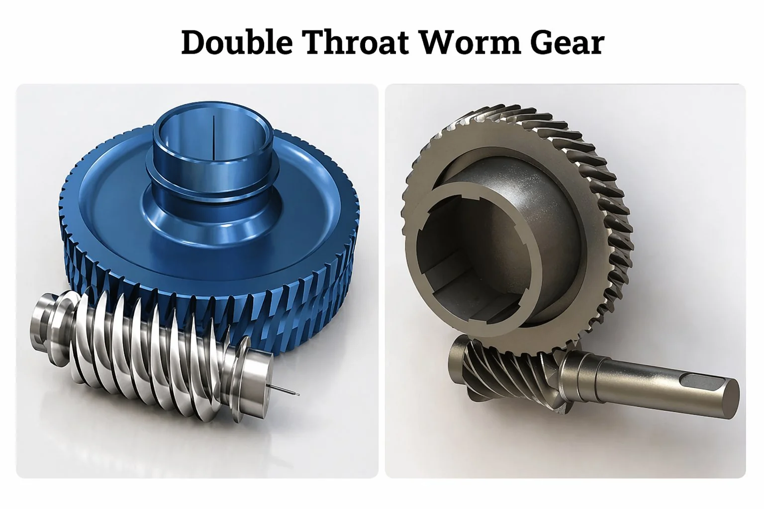
Line-Contact vs Point-Contact vs Double-Throat Arrangements
Three meshing arrangements are possible with a cylindrical worm, and each carries a distinctly different load rating. This comparison is the one our Seoul engineering desk walks customers through when they ask "will the standard set be strong enough?"
| Arrangement | Contact | Load Rating Index | Cost Index | Best Use |
|---|---|---|---|---|
| Worm + helical gear (point) | Point | 40 | 80 | Light loads, simple replacement |
| Worm + worm wheel (line) | Line | 100 | 100 | Standard industrial duty (default) |
| Double-throat (globoidal) | Conjugate line, multi-tooth | 180 – 200 | 140 | Hoists, elevators, heavy reducers |
")
Related Products in the Worm Drive Family
Most Korean buyers order the cylindrical wheel alongside its matched shaft, axial-thrust tapered roller bearings and FKM oil seals as a single sub-assembly. For projects where the whole drive should arrive ready to bolt, a packaged worm gear reducer delivers input and output flanges, oil fill, breather and name-plate — no field assembly required. For motor-integrated applications, the worm gearbox family includes electric motors pre-wired to the input shaft.

Frequently Asked Questions
Q: If equipment failure happens during use, what is the support process?
Email our Seoul desk with photos or a short video of the failed parts plus the original PO number. The engineering team typically responds within one working day with a diagnosis. Parts confirmed as manufacturing defects within the warranty period are replaced at no cost, with Ever-Power paying the outbound freight.
Q: What design software do you work with for custom drawings?
SolidWorks is the primary CAD platform; AutoCAD is used for legacy drawings and machine-shop detailing. We accept STEP, IGES and DXF from customers, and can return fully dimensioned native files or 2D PDFs for approval before machining starts.
Q: How do you control quality from raw material through to despatch?
Three layers. First, incoming raw material is verified against spectrometer samples. Second, skilled machine-tool operators inspect each step during the production process. Third, a dedicated QC department signs off at each process boundary — hobbing, grinding, heat treatment — so defects never accumulate downstream.
Q: What is the correct way to contact the sales team?
Send an enquiry through the website form, email the Seoul office directly, or call the listed number during Korea business hours. Korean, English and Japanese are all supported. Non-business-hour enquiries receive a response on the next working day.
Q: What is your policy on intellectual property?
Customer drawings, logos, artwork and tooling are treated as confidential from the moment they arrive. Signed NDA templates are available on request. Custom tooling is held for exclusive use by the originating customer and never used to supply third parties.
Q: When should I specify an overhead worm arrangement instead of the standard layout?
When peripheral thread speed exceeds 10 m/s, oil-bath lubrication starts to fail because the input shaft cannot lift enough oil from the sump. Moving the wheel above the shaft and adding a splash ring restores proper lubrication and pushes the usable speed up to 15 m/s.
Q: Can I mix a mill-cut wheel with a standard helical hob shaft?
Not recommended. The cutter geometry of a true worm mill matches the axial profile of the thread, producing line contact. A standard helical hob produces a slightly different tooth profile that reduces the contact to a point or small patch. Pairing them degrades load rating by 40 – 60 % and shortens life accordingly.
Customer Feedback
Oh Ye-rim, Packaging Line Engineer, Cheongju (mid 2025)
"Installed a DIN 7 M5 cylindrical set on a carton-erector drive running about 16 hours a day. Contact pattern after the recommended run-in was centred and covered close to 70 % of the tooth face. Five months in, oil-sump temperature settled at 52 °C, well under our 70 °C alarm. The line has not needed unplanned maintenance once."
Bae Hyun-seok, Mechanical Maintenance Chief, Pohang (early 2025)
"We needed replacement wheels for a steel-mill roll-table drive with a failed 1998 unit. Ever-Power measured the damaged wheel on their CMM, produced the drawing inside two days, and shipped a DIN 7 aluminium-iron bronze replacement in 23 days. Unit price was about 55 % of the original European brand. Running eleven months now, noise level is actually quieter than the original."
Takeshi Yamamoto, Plant Engineer, Osaka (late 2025)
"Specified a cylindrical set for a palletising robot base drive. Centre distance was non-standard at 72 mm, which most suppliers would not quote below MOQ 100. Ever-Power accepted a 25-piece first order, machined new tooling inserts, and delivered on time. Tooth contact on assembly was excellent on the first try — no shimming required."
Choi Seo-yeon, Automation Integrator, Suwon (late 2024)
"Three sets installed on a semiconductor wafer-transfer table. DIN 6 accuracy was required for the positioning repeatability. Backlash measured 38 arc-seconds on assembly, inside the 45 arc-second drawing tolerance. The Seoul technical desk answered our lubricant-choice question in Korean within the same day."
Kim Min-jae, Elevator Rebuilder, Busan (early 2026)
"Rebuilt six passenger elevators with new cylindrical worm sets over the past year. Went with tin bronze wheels because the drives run almost continuously during daytime. No galling, no unusual wear on inspection at the six-month mark. The inclusion of the contact-pattern photos in the inspection report was a useful touch — lets us benchmark future wear."
Park Ji-hoon, Solar EPC Project Manager, Jeju (mid 2025)
"Hundreds of tracker drives across two sites. Selected the double-throat option on the heavier frames because the wind-load swings are significant. The higher upfront cost pays for itself in the avoided mid-cycle replacements that our earlier projects experienced with cheaper single-throat sets. Two seasons in, no failures."
Additional information
| Editor | Cxm |
|---|
Related products
-
Alloy Steel Worm and Worm Gear for Auto Parts | Ø5-Ø120 Module 0.2-2.2
-
Stainless Steel Worm Gear for CNC Machinery | DIN 5 SCM415
-
Duplex Worm Gear Set | Dual-Lead Zero-Backlash Worm Drive
-
Brass Worm Wheel & Shaft Set | 20-Tooth M0.5 Micro Gear Kit
-
Custom Worm Gear Sets | Worm Drive
-
Worm and Wheel Sets | DIN6 Worm Gearing
-
Plastic Worm Gears for Micro Drives | POM & Nylon Gear Sets


