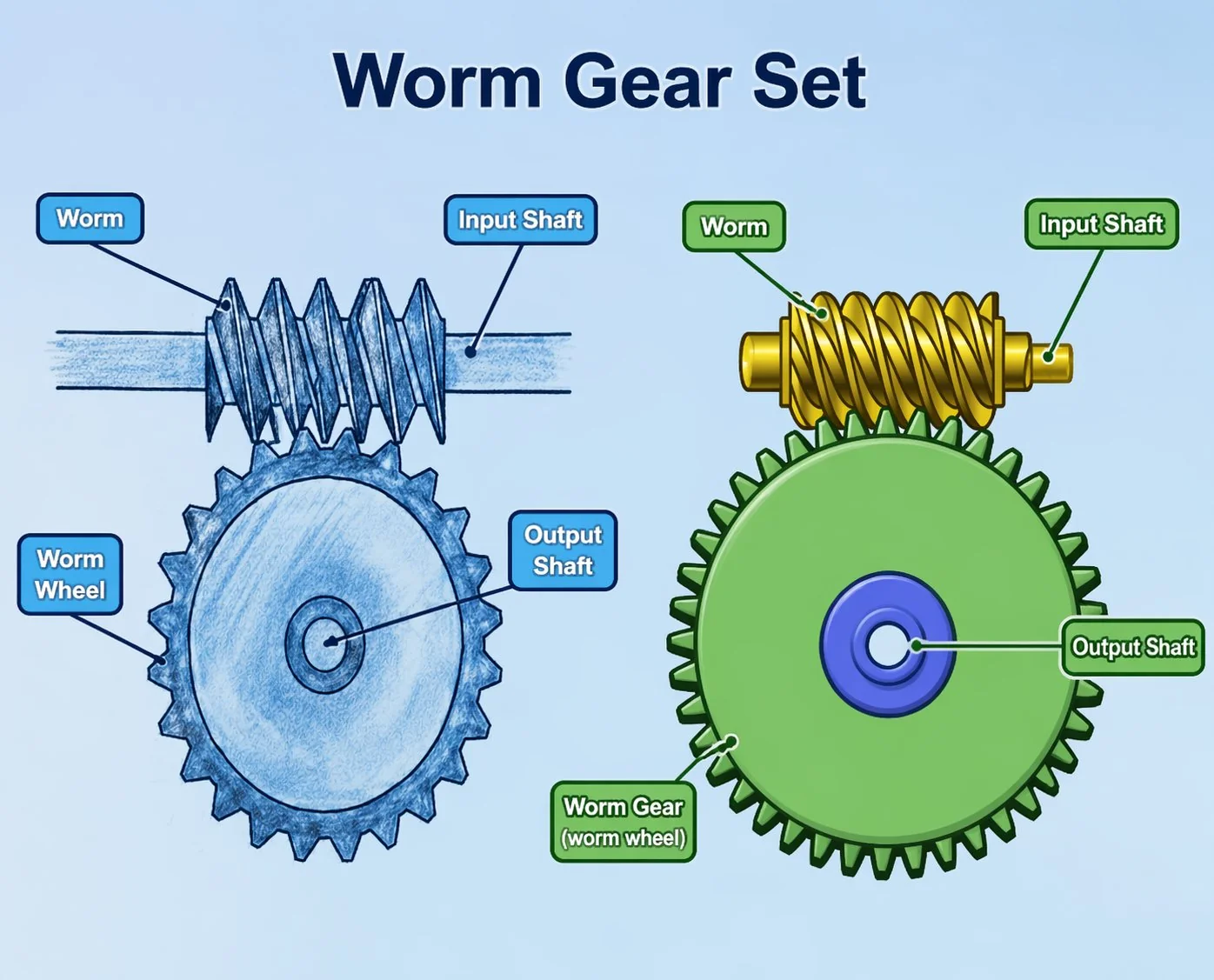
Ausfallarten von Schneckengetrieben – Verschleiß, Lochfraß und Zahnbruch
Ein Handbuch zur Felddiagnose. Wie die einzelnen Fehler durch die Inspektionsöffnung aussehen, wie sie sich am Motor anhören und was sie verursacht hat, bevor Sie das Schneckenrad austauschen.
Fünf Ausfallursachen sind für nahezu jeden Ausfall eines Schneckengetriebes verantwortlich: abrasiver Verschleiß (allmählich, staubbedingt), adhäsiver Verschleiß oder Fressen (plötzlich, schmierstoffbedingt), Lochfraß (zyklische Belastungsermüdung, entsteht über Tausende von Stunden), plastische Verformung (Überlastung, entsteht innerhalb von Sekunden) und Zahnbruch (endgültig, trifft jeden unerwartet). Jede dieser Ursachen hinterlässt charakteristische Spuren auf der Oberfläche des Schneckenrads. Das korrekte Erkennen dieser Spuren bei einer geplanten Inspektion entscheidet darüber, ob eine 30-minütige vorbeugende Maßnahme zu einer 6-stündigen Notfallreparatur führt. Der häufigste Grund für einen erneuten Ausfall desselben Antriebs drei Monate später ist der Austausch von Teilen ohne vorherige Diagnose der Ausfallursache.
Erst diagnostizieren, dann ersetzen
Die meisten Schneckengetriebeausfälle, zu deren Untersuchung wir gerufen werden, weisen eine Gemeinsamkeit auf: Die Teile wurden bereits einmal ausgetauscht, und derselbe Antrieb fällt innerhalb etwa desselben Zeitraums erneut aus. Das Wartungsteam identifizierte das defekte Bauteil, tauschte es gegen ein neues aus und betrachtete den Fall als abgeschlossen. Sechs bis zwölf Monate später weist das neue Schneckenrad dasselbe Verschleißbild auf wie das defekte. Das ist kein Problem der Bauteilqualität, sondern eine Fehldiagnose.
Jeder Ausfall eines Schneckenrades hinterlässt Spuren an den Zahnflanken. Muster, Lage und Tiefe der Beschädigung geben Aufschluss über den physikalische Mechanismus, der den Ausfall verursacht hat. Kennt man den Mechanismus, kann man die eigentliche Ursache (Überlastung, falsches Schmiermittel, Verunreinigung, Fehlausrichtung, Vibration) beheben, anstatt immer wieder Teile auszutauschen. Dieser Artikel beschreibt die fünf Ausfallarten, die nahezu alle Schneckenradausfälle abdecken, wie diese bei einer Zahnflankenprüfung aussehen, was der Bediener üblicherweise vor dem Ausfall meldet und welche Korrekturmaßnahmen erforderlich sind.
Modus 1 – Abrasiver Verschleiß
Abrasiver Verschleiß ist die langsamste und am besten vorhersehbare Ausfallursache bei Schneckengetrieben. Harte Partikel im Schmierstoff – typischerweise Staub, Schleifspäne, Oxidrückstände aus dem Einlaufprozess oder Verunreinigungen durch einen beschädigten Öldichtring – gelangen in die Kontaktzone zwischen Schnecke und Rad und beschädigen beide Oberflächen. Das Bronzerad ist stärker betroffen als die Stahlschnecke, da Bronze das weichere Material ist.
Die Zahnflanken weisen parallele, in Gleitrichtung verlaufende Kratzer auf, die über die gesamte aktive Flanke gleichmäßig verteilt sind und keine Grübchen oder Kraterbildungen aufweisen. Das Zahnprofil des Schneckenrades dünnt sich allmählich aus – messbar als Zunahme des Zahnflankenspiels am Schneckenradkranz über mehrere Betriebsmonate.
Beschwerde des Betreibers: „Das Getriebe wird lauter“ – typisch 3 bis 6 Monate vor dem Ausfall. Das Zahnflankenspiel nimmt hörbar zu, wenn sich die Last umkehrt; die Ölwechselintervalle verkürzen sich, weil das Öl schneller dunkel wird als üblich.
Hauptursachen: Eine beschädigte Öldichtung, durch die Staub eindringen kann, eine staubbelastete Umgebung mit unzureichender Dichtungskonstruktion, Verunreinigungen beim Nachfüllen von Öl oder ein versäumter Ölwechsel, der zur Ansammlung von Abriebpartikeln führt, können die Ursache für Verschleiß sein. Seltener entsteht abrasiver Verschleiß dadurch, dass Einlaufpartikel nicht von einem Magnetstopfen oder Filter aufgefangen werden.
Korrekturmaßnahme: Getriebeölwanne entleeren und spülen. Beschädigte Dichtungen ersetzen; Dichtungsdesign verbessern (Lippendichtung plus Staublippe oder Labyrinthdichtung für stark staubige Umgebungen). Falls noch nicht vorhanden, eine magnetische Ablassschraube nachrüsten. Ölprobenentnahmeventil installieren und ein Ölanalyseprogramm starten. Schneckenrad ersetzen, wenn das gemessene Zahnflankenspiel 50 % der ursprünglichen Spezifikation überschreitet – Verschleiß darüber hinaus führt zum Verlust des ursprünglichen Zahnprofils und beschleunigt den Ausfall.
Modus 2 – Klebstoffverschleiß und Abrieb
Adhäsiver Verschleiß führt bei starker Ausprägung zu Riefenbildung – manchmal auch als Schneckenverschleiß bezeichnet. Während abrasiver Verschleiß sich über Monate hinweg allmählich entwickelt, entsteht Riefenbildung innerhalb von Sekunden. Der Schmierfilm reißt, Schnecke und Schneckenrad berühren sich unter hohem Druck direkt mit Metall, durch Reibungshitze verschweißen sich winzige Metallstellen, und diese Verschweißungen lösen sich bei der nächsten Umdrehung wieder. Das Ergebnis ist eine raue, rissige und verschmierte Beschädigung, die den polierten Zahnflanken eines intakten Schneckenrades in keiner Weise ähnelt.
Die Zahnflanken weisen markante, matte Streifen in Gleitrichtung auf. Die beschädigten Bereiche sind aufgrund lokaler Erhitzung oft bläulich oder mattgrau verfärbt. Die Beschädigungen konzentrieren sich typischerweise in der Nähe der Zahnspitzen oder -wurzeln, wo die Gleitgeschwindigkeit am höchsten ist, oder an einem Ende der Zahnbreite, wenn das Zahnradpaar nicht fluchtet. Unter Vergrößerung erscheint die Oberfläche eher gerissen und verschmiert als zerkratzt.
Beschwerde des Betreibers: Plötzlicher Temperaturanstieg am Getriebegehäuse, oft schon wenige Stunden nach dem Anfahren. Brandgeruch von heißem Öl. Der Antrieb kann unter normaler Last blockieren. Bis der Bediener dies bemerkt, ist der Schaden bereits entstanden.
Hauptursachen: Falsche Schmierstoffviskosität (zu dünnflüssig für die Betriebstemperatur), niedriger Ölstand, der beim Kaltstart zu Trockenlauf der Schnecke führt, starke Überlastung, die den Schmierfilm zerstört, oder – bei älteren Konstruktionen – Einlauf ohne Einlauföl mit geeignetem Anti-Schleifmittelzusatz. Scheuerstellen an einem Ende der Schneckenwelle deuten fast immer auf eine Fehlausrichtung der Schneckenwelle zur Schneckenradachse hin, die die Standardtoleranz von 0,0005 Zoll pro Zoll überschreitet.
Korrekturmaßnahme: Tauschen Sie sowohl Schnecke als auch Schneckenrad aus – Beschädigungen an einem der beiden Bauteile führen nach Wiederinbetriebnahme schnell zu weiteren Schäden am Gegenstück. Überprüfen Sie die Schmierstoffsorte anhand der tatsächlichen Betriebstemperatur; wechseln Sie von Mineralöl auf PAO-Synthetiköl, wenn die Ölwannentemperatur vor dem Ausfall 80 °C überschritten hat. Prüfen Sie den Ölstand anhand der tatsächlichen Einbaulage. Überprüfen Sie vor dem Zusammenbau mit einer Messuhr die Rechtwinkligkeit der Welle zur Achse. War Überlastung die Ursache, beheben Sie die Probleme – tauschen Sie nicht nur Teile aus.
Modus 3 — Pitting
Lochfraß ist eine Form der Kontaktspannungsermüdung – kleine Krater entstehen auf der Zahnoberfläche, wo zyklische Spannungen unterirdische Risse verursachen, bis das Metall zwischen Riss und Oberfläche bricht. Jeder Lochfraß ist das Ergebnis von Millionen von Lastwechseln. Bei Schneckengetrieben tritt Lochfraß typischerweise am Bronzerad, nicht an der Stahlschnecke auf, da das Rad pro Umdrehung etwa die gleiche Anzahl an Zyklen erfährt wie die Schnecke, das weichere Material jedoch pro Zyklus stärkeren Kontaktspannungsschäden ausgesetzt ist.
Die Zahnflanken weisen kleine, runde oder ovale Krater mit einem Durchmesser von typischerweise 0,5 bis 3 Millimetern auf, die über die Kontaktfläche verteilt sind. Anfängliche Lochfraßbildung kann sich stabilisieren, sobald die Erhebungen abgetragen sind und sich die Last neu verteilt. Fortschreitende Lochfraßbildung deutet darauf hin, dass die Kontaktspannung weiterhin zu hoch ist.
Beschwerde des Betreibers: Es kommt zu verstärkten Vibrationen und Geräuschen, die sich über Tausende von Betriebsstunden allmählich entwickeln. Die Schwingungsanalyse zeigt erhöhte Amplituden bei der Eingriffsfrequenz des Schneckengetriebes und deren Oberschwingungen. Der Antrieb funktioniert zwar noch, wird von den Bedienern aber als „rau“ oder „störanfällig“ beschrieben.
Hauptursachen: Die Kontaktspannung liegt dauerhaft über der Dauerfestigkeitsgrenze des Radmaterials. Dies bedeutet in der Regel, dass die Anwendung den Antrieb stärker belastet als ursprünglich vorgesehen – beispielsweise durch ein erhöhtes Drehmoment, einen längeren Betriebszyklus oder weil das Radmaterial am unteren Ende des zulässigen Festigkeitsbereichs ausgelegt war. Ältere Räder können auch bei korrekter Belastung aufgrund der akkumulierten Lastwechsel Lochfraß entwickeln, da sie das Ende ihrer Lebensdauer erreicht haben.
Korrekturmaßnahme: Leichte anfängliche Lochfraßbildung (weniger als 1 % der Kontaktfläche) ist oft ein normales Einlaufphänomen und stabilisiert sich nach dem Einlaufen. Fortschreitende Lochfraßbildung (mehr als 5 % der Kontaktfläche, zunehmend mit jedem Inspektionszyklus) erfordert ein Eingreifen. Optionen: Reduzierung der Anwendungsleistung, Verwendung eines robusteren Felgenmaterials (z. B. zentrifugalgegossene Bronze statt Sandguss oder Aluminiumbronze statt Phosphorbronze) oder Umstellung auf eine größere Rahmengröße. Der Austausch beschädigter Teile durch solche mit denselben Spezifikationen führt innerhalb einer ähnlichen Betriebsdauer zum gleichen Ausfall.
Modus 4 — Plastische Verformung
Plastische Verformung ist eine Überlastungsschädigung, die einen Zahn zwar nicht vollständig abbricht, ihn aber dauerhaft verformt. Bronze ist weicher und verformt sich daher schneller als Stahl. Während Lochfraß sich über Tausende von Stunden entwickelt, kann plastische Verformung bereits durch ein einziges Stoßereignis auftreten – beispielsweise durch plötzliches Blockieren, kurzzeitigen Überstrom im Motor oder einen Endanschlag auf einen Positionierer.
Die Zahnflanken weisen Fließverformungen auf – die Arbeitsfläche ist leicht eingedrückt, wobei verdrängtes Metall an der Zahnspitze oder -wurzel eine kleine Lippe bildet. Dies wird mitunter als „Wälzen“ der Zahnoberfläche bezeichnet. Das ursprüngliche Zahnprofil ist nicht mehr erkennbar. Die Zahnflankenspielmessungen zeigen uneinheitliche Werte am Rad – einige Zähne weisen normales Spiel auf, andere hingegen ein zu geringes, da die Verformung ihre Teilung verändert hat.
Beschwerde des Betreibers: Typischerweise tritt dies nach einem bekannten Vorfall auf – einem blockierten Antrieb, einer ausgelösten Überstromsicherung oder einem Unfall. Manchmal gibt es keine Beanstandung, bis bei der nächsten Routineinspektion unregelmäßige Zahnprofile festgestellt werden. Der Antrieb kann zwar weiterlaufen, da sich die Zähnezahl und das Übersetzungsverhältnis nicht geändert haben, aber das Eingriffsmuster ist nun ungleichmäßig, und die Lochfraßkorrosion beschleunigt sich.
Hauptursachen: Stoßbelastungen, die die Streckgrenze der Bronze überschreiten. Typische Szenarien: Eine Hebezeuglast verhakt sich plötzlich an einem Hindernis; ein Förderband blockiert, woraufhin der Motor versucht, die Blockierung mit vollem Drehmoment zu lösen; ein Aktor trifft auf einen harten Endanschlag ohne Soft-Stop im Steuerungssystem; eine Winde, bei der sich das Seil verhakt und dann plötzlich loslässt. Die ausgelegten Betriebsfaktoren sind darauf ausgelegt, eine moderate Überlastung abzufangen; sie halten jedoch nicht kurzzeitigen Belastungen stand, die ein Vielfaches der Nennlast betragen.
Korrekturmaßnahme: Das Schneckenrad muss ausgetauscht werden – verformte Zähne richten sich nicht wieder aus. Prüfen Sie die Schneckenwelle auf das gleiche Muster und tauschen Sie sie gegebenenfalls aus. Am wichtigsten ist jedoch die Anpassung der Anwendung: Installieren Sie einen Drehmomentbegrenzer, eine elektronische Überstromabschaltung, weiche Endanschläge in der Steuerungssoftware oder eine mechanische Sicherung wie einen Scherbolzen. Die nächste Überlastung wird die neuen Teile auf die gleiche Weise verformen.
Modus 5 — Zahnbruch
Zahnbruch ist der endgültige Ausfallmechanismus – ein oder mehrere Zahnräder brechen physisch ab. Der Antrieb stoppt oder läuft unrund, da die abgebrochenen Zähne im Getriebe herumschlagen. Zwei unterschiedliche Mechanismen verursachen Zahnbruch: Biegeermüdung (langsam, nach akkumulierten Lastwechseln) und Überlastbruch (plötzlich, nach einer einzelnen, übermäßigen Belastung).
Bei Biegeermüdungsbrüchen zeigt die Bruchfläche zwei deutlich unterscheidbare Zonen: einen glatten Bereich mit gekrümmten Bruchkanten, wo sich der Riss zyklisch fortpflanzte, und einen rauen Bereich, wo der endgültige, instabile Bruch in einem einzigen Lastzyklus erfolgte. Der Riss entsteht typischerweise am Zahnfußansatz der belasteten Flanke, wo die Biegespannung konzentriert ist. Oft weisen mehrere Zähne ähnliche Schäden in unterschiedlichen Stadien der Rissausbreitung auf.
Bei Überlastungsfrakturen zeigt sich eine einzelne, raue Bruchfläche ohne Bruchspuren. Oft bricht nur ein Zahn. Der Bruch kann auch anders verlaufen als quer zur Zahnwurzel, wenn die Überlastung ungewöhnliche Spannungen verursacht hat – beispielsweise kann ein Zahn entlang seiner gesamten Zahnbreite spalten, wenn sich ein Fremdkörper im Zahngeflecht verklemmt.
Beschwerde des Betreibers: Bei Biegeermüdung tritt dieselbe Vibrationsprogression wie bei Lochfraß auf, die mit einem plötzlichen Geräusch und Antriebsstillstand endet. Bei Überlastbruch ist ein hörbarer Knall zu vernehmen, gefolgt von Antriebsstillstand – üblicherweise im Moment der Überlastung.
Hauptursachen: Bei Biegeermüdung entsteht dieselbe chronische Überlastung wie bei Lochfraß, nur über einen anderen Spannungspfad. Die Zahnwurzel wird bei jedem Zyklus auf Zug beansprucht; überschreitet diese Zugkraft die Dauerfestigkeitsgrenze der Bronze, entsteht schließlich ein Riss. Bei Überlastungsbruch handelt es sich um ein einzelnes, kurzzeitiges Ereignis – ähnlich wie bei plastischer Verformung, jedoch mit einer so hohen Belastung, dass der Zahn bricht, anstatt sich nur zu verbiegen.
Korrekturmaßnahme: Schnecke und Schneckenrad zusammen austauschen – abgebrochene Zähne erzeugen Metallspäne, die mit hoher Wahrscheinlichkeit die Gewindeflächen der Schnecke beschädigt haben. Getriebeöl ablassen, spülen und neu befüllen, um die Späne zu entfernen; Gehäuse auf Stoßschäden prüfen. Die Anwendung wie bei plastischer Verformung behandeln. Eine Vergrößerung der Schneckenradbreite, ein größerer Modul oder eine höhere Festigkeit (z. B. Aluminiumbronze) erhöhen die Biegeermüdungsfestigkeit, wenn die Ursache chronische hohe Belastungszyklen waren.
Kurzübersicht – Diagnose auf einen Blick
Nachdem Sie die Inspektionsabdeckung entfernt und die Zähne des Schneckenrads begutachtet haben, lässt sich der Fehler anhand der sichtbaren Beschädigungen in der Regel innerhalb von Sekunden einem der fünf Fehlermodi zuordnen. Nachfolgend finden Sie die Feldreferenzmatrix, die unsere Wartungskunden ausdrucken und in ihren Werkzeugkasten kleben.
Wenn uns ein Wartungsteam ein defektes Schneckenrad zusendet und um Ersatz bittet, fordern wir vor dem Versand immer zwei Fotos an: die abgenutzte Zahnflanke bei guter Beleuchtung und die Bruchfläche der abgebrochenen Zähne, falls Zähne fehlen. In etwa 30 Prozent der Fälle zeigen die Fotos einen Fehler, der auf ein systembedingtes Problem der Anwendung und nicht auf einen Defekt des Bauteils hinweist. Ein neues Schneckenrad ohne Ursachenanalyse zu versenden, garantiert, dass der Ersatz auf die gleiche Weise ausfällt. Zehn Minuten für das Fotografieren der defekten Teile vor der Entsorgung sind die günstigste Versicherung gegen einen erneuten Ausfall.
Drei reale Versagensuntersuchungen

Untersuchung 1 – Koreanische Stanzpresse, wiederholter Radausfall
In einem Stanzwerk traten am Schneckenrad eines Bandförderers etwa alle 4.000 Betriebsstunden Ausfälle auf – drei Austausche innerhalb von 18 Monaten. Fotos des letzten Ausfalls zeigten vergossenes Metall an den Zahnspitzen und ungleichmäßiges Zahnflankenspiel. Diagnose: Plastische Verformung durch wiederholte Endanschläge beim Erreichen des mechanischen Anschlags. Der ursprüngliche Antrieb war für ein konstantes Drehmoment ausgelegt, ohne die Stoßspitzen beim Anfahren zu berücksichtigen. Lösung: Installation einer elektronischen Sanftanlauffunktion in der Pressensteuerung, um den Förderer vor dem mechanischen Kontakt abzubremsen. Mit der neuen Steuerung erreichte das nächste Schneckenrad 28.000 Betriebsstunden vor dem planmäßigen Austausch – eine siebenfache Verbesserung ohne weitere Teileänderungen außer dem Schneckenrad selbst.
Untersuchung 2 – Japanischer Mixer, Abriebspuren innerhalb des ersten Monats
Ein OEM für pharmazeutische Anlagen meldete innerhalb von 600 Betriebsstunden Verschleißschäden am Schneckenrad eines Edelstahl-Mischerantriebs. Fotos zeigten matte Streifen, die sich an einem Ende der Zahnbreite konzentrierten – ein typisches Anzeichen für eine Fehlausrichtung. Diagnose: Der Antrieb war werkseitig mit dem Gehäuse auf einer ebenen Vorrichtung ausgerichtet worden, der Kunde hatte ihn jedoch auf einem leicht verdrehten Grundrahmen montiert. Die Abweichung von 0,0008 Zoll pro Zoll von der Senkrechten überschritt die Toleranz von 0,0005 Zoll pro Zoll. Die konzentrierte Last an einer Zahnflanke führte zu einem lokalen Ölfilmabriss und schnellem Verschleiß. Lösung: Der Grundrahmen wurde unterlegt, um innerhalb der Toleranz zu liegen, das beschädigte Schneckenradpaar wurde ausgetauscht, und der überholte Antrieb lief anschließend ohne weitere Probleme. Fazit: Die Ausrichtung muss erst nach der Montage des Getriebes auf der endgültigen Montagefläche überprüft werden, nicht im Werk vor dem Versand.
Untersuchung 3 – Vietnamesisches Zementwerk, fortschreitende Lochfraßkorrosion
Ein Zementhersteller meldete über einen Zeitraum von 14 Monaten zunehmende Vibrationen an einem Förderbandantrieb für Zementschlamm. Bei einer planmäßigen Inspektion wurden messbare Lochfraßkorrosion festgestellt. Fotos zeigten, dass etwa 8 Prozent der Kontaktfläche mit kleinen Kratern im Bereich von 1 bis 2 Millimetern bedeckt waren. Diagnose: fortschreitende Lochfraßkorrosion durch Kontaktspannung, ein Hinweis auf chronische Überlastung. Die Untersuchung ergab, dass das Förderband 18 Prozent mehr Material pro Stunde transportiert hatte als ursprünglich vorgesehen. Der Bediener hatte die Bandgeschwindigkeit erhöht, um die geänderten Produktionsziele zu erreichen, ohne den Antrieb entsprechend anzupassen. Lösung: Rückführung des Durchsatzes auf die ursprüngliche Spezifikation und Betrieb des Antriebs bis zum planmäßigen Austausch nach Erreichen der Ermüdungslebensdauer oder Aufrüstung des Schneckenrades auf Aluminiumbronze (CuAl10Fe5Ni5) für den neuen Durchsatz. Der Kunde entschied sich für die Aufrüstung, und der überholte Antrieb läuft nun seit über zwei Jahren ohne weitere Lochfraßkorrosion.
Häufig gestellte Fragen
F: Wie kann ich Lochfraß von Korrosionsschäden unterscheiden?
Lochfraßkrater sind annähernd kreisförmig oder oval, befinden sich innerhalb der aktiven Kontaktzone an der Zahnflanke und konzentrieren sich dort, wo die Kontaktspannung am höchsten ist. Korrosionsschäden (durch falsche Ölzusammensetzung, die Bronze angreift) zeigen sich als verfärbte Stellen sowohl außerhalb als auch innerhalb der Kontaktzone, oft mit grünen oder schwarzen Oberflächenbelägen, und sind nicht an bestimmten Spannungsstellen konzentriert. Weisen die unbeschädigten Laufflächen des Rades die gleiche Verfärbung wie die Kontaktfläche auf, ist Korrosion wahrscheinlich. Ist nur die Kontaktzone beschädigt, ist Lochfraß wahrscheinlich.
F: Soll ich die defekten Teile zur Analyse an den Lieferanten zurücksenden?
Bei Garantieansprüchen ist dies der Fall – die meisten seriösen Schneckengetriebehersteller analysieren defekte Teile und erstellen einen schriftlichen Bericht. Bei wiederkehrenden Ausfällen desselben Antriebs, auch außerhalb der Garantiezeit, kann eine metallurgische Analyse klären, ob das Material des Laufrads den ursprünglichen Spezifikationen entsprach oder unterdurchschnittlich war. Die Kosten für die Analyse (in der Regel einige hundert US-Dollar) sind im Vergleich zu einem wiederkehrenden Ausfallmuster vernachlässigbar. Senden Sie zunächst aussagekräftige Fotos; der Lieferant kann anhand der Bilder meist schon beurteilen, ob eine physikalische Analyse sinnvoll ist.
F: Ist die gelegentliche Bildung kleiner Grübchen während des Einbrennens normal?
Ja. Bronzene Schneckenräder weisen typischerweise in den ersten 100 bis 500 Betriebsstunden leichte Oberflächenverformungen und geringfügige Lochfraßbildung auf, da sich das Kontaktmuster einläuft. Diese Einlaufnarben stabilisieren sich in der Regel, sobald die stark beanspruchten Stellen abgetragen sind. Lochfraß, der nach 1000 Betriebsstunden weiter zunimmt oder 2 bis 3 Prozent der Kontaktfläche überschreitet, ist kein Einlauf mehr, sondern ein Zeichen fortschreitender Kontaktspannungsermüdung und deutet auf chronische Überlastung hin. Diese Unterscheidung ist wichtig: Einlaufnarben sind unbedenklich, fortschreitende Lochfraßbildung ist ein Warnsignal.
F: Kann eine Schwingungsanalyse den Ausfall eines Schneckengetriebes vorhersagen, bevor sichtbare Schäden auftreten?
Bei Lochfraß und Biegeermüdung zeigen Schwingungsspektren erhöhte Amplituden bei der Eingriffsfrequenz des Schneckengetriebes und deren Harmonischen, wenn der Schaden fortschreitet. Der Trend über Monate ist in der Regel ein zuverlässigerer Indikator als ein einzelner absoluter Messwert. Plötzliche Ausfälle (Fressverschleiß, Überlastbruch) treten oft zu schnell auf, als dass die Schwingungsüberwachung sie rechtzeitig erfassen könnte. Die Ölanalyse ist ergänzend: Steigende Bronzepartikelzahlen im Schmierstoff deuten auf aktiven Verschleiß hin, bevor Zahnflankenschäden sichtbar werden. Eine monatliche Schwingungsprüfung in Kombination mit einer vierteljährlichen Ölanalyse deckt die meisten fortschreitenden Ausfälle mit einer Vorwarnzeit von Wochen oder Monaten auf.
F: Wie ändert sich das Ausfallverhalten bei einzelnen Zahnradsätzen im Vergleich zu kompletten Getrieben?
Ausfälle von Zahnradsätzen ohne Anbauteile deuten darauf hin, dass das kundenspezifisch gefertigte Gehäuse eine mögliche Fehlerquelle darstellt – Ebenheit der Montage, Ausrichtung, Schmierstofffüllstand, Dichtungsqualität und Lagerauswahl sind allesamt vom Kunden beeinflussbare Variablen. Komplett Schneckengetriebe Fehler isolieren die Variablen auf die vom Zulieferer kontrollierte Fertigung, was die Diagnose vereinfacht. Die fünf Fehlermodi selbst sind in beiden Ausführungen identisch – was sich ändert, ist die Menge der wahrscheinlichen Ursachen. Fehlausrichtung tritt häufiger bei Installationen mit blanken Zahnradsätzen auf; Schmierstoffprobleme sind in beiden Ausführungen etwa gleich häufig; Überlastungsursachen sind anwendungsabhängig und unabhängig von der Ausführung.
F: Versagt die Schneckenwelle anders als das Schneckenrad?
Das Schneckenrad versagt fast immer zuerst, da die Bronze weicher ist und schneller Ermüdungsschäden entwickelt als die gehärtete Stahlschnecke. Versagt die Schneckenwelle, sind die häufigsten Ursachen Fressen (starker Schmierstoffverlust) und Oberflächenermüdung (sehr hohe Dauerbelastung über Tausende von Stunden). Zahnbrüche an der Schneckenwelle sind selten, es sei denn, ein Fremdkörper verklemmt sich im Eingriff und beschädigt ein Gewinde. Vorgehensweise beim Austausch: Schnecke und Schneckenrad sollten immer als zusammengehöriges Paar ersetzt werden, wenn eines der beiden Bauteile ausfällt. Läuft ein neues Schneckenrad gegen eine verschlissene Schnecke, tritt das ursprüngliche Ausfallmuster innerhalb eines Bruchteils der geplanten Lebensdauer des neuen Bauteils erneut auf.
F: Wann ist ein defektes Schneckenrad noch reparierbar?
Nahezu nie. Bronze lässt sich nicht zuverlässig auf das ursprüngliche Zahnprofil schweißen; selbst wenn die Geometrie wiederhergestellt werden kann, ist die Dauerfestigkeit der Reparaturzone unvorhersehbar. In fast allen Fällen ist der Austausch die wirtschaftlich sinnvollste Entscheidung. Sehr große Industrieräder (über 800 Millimeter Teilkreisdurchmesser) lassen sich unter Umständen wirtschaftlich nachbearbeiten – die verschlissene Oberfläche wird abgedreht und ein Zahnprofil mit kleinerem Modul neu geschnitten –, dies erfordert jedoch ein Rad mit zusätzlicher Materialstärke. Standardmäßige Katalogräder sind nicht für die Nachbearbeitung ausgelegt.
Die Diagnose der Fehlerursache entscheidet über eine dauerhafte Reparatur oder einen erneuten Ausfall. Die fünf oben beschriebenen Fehlerursachen sind für nahezu jeden Schneckenradausfall verantwortlich, der uns in der Technikabteilung erreicht. Die visuelle Signatur des defekten Schneckenrads lässt sich in wenigen Minuten erkennen, sobald man weiß, worauf zu achten ist, und gibt Aufschluss darüber, ob das nächste Ersatzteil länger hält als das defekte. Werden Teile ausgetauscht, ohne die Fehlerursache zu kennen, ist ein erneuter Ausfall innerhalb eines ähnlichen Zeitraums garantiert.
Für koreanische und japanische OEM-Entwicklungsteams, die wiederkehrende Schneckengetriebeausfälle untersuchen, analysiert unsere Entwicklungsabteilung Fotos der Zahnflanken, identifiziert die Ausfallursache und empfiehlt sowohl Ersatzteile als auch die Anwendungsänderung, die ein erneutes Auftreten verhindert. Standardkatalog Schneckenradsätze aus Phosphorbronze und Aluminiumbronze Liefern Sie mit Materialzertifikaten, die die Fehlermodusanalyse bei Gewährleistungsansprüchen unterstützen – fordern Sie ein Überprüfung der Fehlermodi Senden Sie uns bitte Fotos der defekten Teile, und unser Team wird Ihnen innerhalb eines koreanischen Werktags eine schriftliche Diagnose zukommen lassen.
Wiederkehrender Fehler auf demselben Laufwerk?
Bitte senden Sie uns zwei bis drei Fotos der defekten Schneckenradzähne, ein Foto der Bruchfläche eines Zahnes sowie eine Beschreibung des Betriebszyklus. Wir werden die Fehlerursache ermitteln und Ihnen sowohl die Ersatzteile als auch die Anwendungsänderung empfehlen, die ein erneutes Auftreten verhindert.
Herausgeber: Cxm


