Korea Ever-Power · Application Engineering Guide
Vis sans fin et roue dentée pour entraînements de pont roulant et de palans
A crane worm gear pair that fails to hold is a crane that releases its load. Every person standing beneath a suspended beam, coil, or mould trusts their life to the self-locking threshold of a single gear pair. The FEM duty group classification exists to match that gear pair to the severity of the crane’s working life — and getting the group wrong means either over-spending or under-protecting.
All crane and hoist worm gear pairs must be single-start with strong self-locking (lead angle 2 to 5 degrees) and a separate mechanical brake as redundant holding. The specification is anchored in the FEM duty group classification (ISO 4301), which maps crane usage intensity to service factor, material grade, inspection interval, and design life. FEM group 1Bm (workshop crane, 200 hours per year) requires SF 1.5 and standard materials. FEM group 4m (steel mill ladle crane, 4,000 hours per year) requires SF 2.5, centrifugal-cast bronze, and 6-month inspection intervals. Emergency stop shock factor for all crane hoist drives is 2.5 to 3.0 times rated torque — this single transient event is often the binding sizing constraint, not the steady-state lifting torque. Marine and port cranes add corrosion resistance requirements (aluminium bronze wheel, stainless or zinc-plated worm) on top of the mechanical specification.
Why crane hoists depend on worm gear self-locking
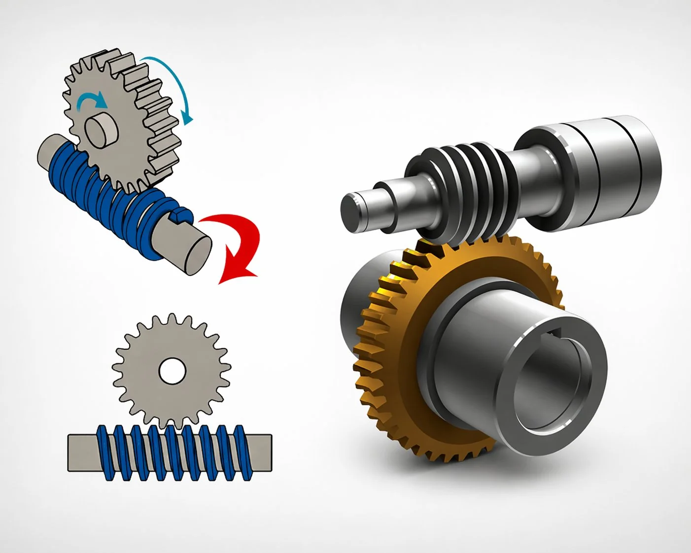
Every overhead crane, gantry crane, jib crane, and portable hoist that lifts a load above ground level shares one non-negotiable safety requirement: the load must not fall if drive power is lost. This requirement has governed crane hoist drive selection for over a century, and the worm gear pair remains the dominant solution because it delivers mechanical self-locking as an inherent geometric property rather than as an add-on component.
The physics is direct: a suspended load applies a constant gravitational torque to the hoist drum shaft. If the gear pair between the motor and the drum allows reverse rotation (back-driving), the load accelerates downward. A single-start worm gear pair with lead angle below the friction angle physically cannot rotate in reverse — the friction at the tooth contact exceeds the driving component of the gravitational force, and the system locks.
This geometric lock is independent of electrical power, control system status, or brake condition. It functions even when every other safety system has failed — which is why crane standards (EN 13001, ISO 4301, FEM rules) treat it as the primary holding mechanism and require a separate mechanical brake only as redundancy.
Helical gear pairs offer 95+ percent efficiency but cannot self-lock — every helical-geared hoist depends entirely on an electrically-released brake as the sole holding mechanism. Planetary sets are similarly non-locking. The worm gear pair at 40-55 percent efficiency is the least efficient option, but it is the only one where geometry itself prevents load fall. For crane applications, this safety property outweighs the efficiency penalty because the consequence of failure (dropped load, potential fatality) dwarfs any energy cost.
FEM duty group — mapping crane usage to worm gear pair specification
The Federation Europeenne de la Manutention (FEM) classification system, adopted into ISO 4301, divides cranes into duty groups based on two factors: the total number of operating cycles over the crane’s design life and the load spectrum (what fraction of lifts are at or near the safe working load versus light loads). The duty group directly determines the service factor, material grade, and inspection schedule for the hoist worm gear pair.
The table below maps FEM duty groups to worm gear pair specification parameters. This is the selection tool that connects the crane application to the gear pair order.
The progression from group 1Bm to 5m doubles the service factor (1.5 to 3.0), upgrades from gravity-cast to centrifugal-cast bronze, shifts the worm from case-hardened to through-hardened steel, and compresses the inspection interval from annual to monthly. Each step reflects a real increase in cumulative fatigue loading: a 5m scrap yard crane sees more load cycles in one month than a 1Bm workshop crane sees in a year. The worm gear pair for each must be proportionally rigorous.
The most common specification error in crane procurement is applying a light-duty service factor to a moderate or heavy-duty crane. A factory crane that runs two shifts per day with frequent near-SWL lifts is not a 1Am crane — it is at least 2m, possibly 3m. Under-classifying the duty group by one or two steps means the worm gear pair is sized 25 to 50 percent below the actual fatigue requirement. The pair passes commissioning tests easily (new pairs always have margin) but develops accelerated wear after 18 to 36 months as the cumulative fatigue damage catches up with the undersized specification.
Emergency stop shock — the transient that often governs sizing
Steady-state lifting torque is not the worst case for a crane hoist worm gear pair. The worst case is the emergency stop: the crane is lowering a load at full speed, the operator hits the emergency stop button, the motor brake engages, and the rotating mass of the hoist drum, coupling, and worm shaft decelerates from full speed to zero in 0.5 to 1.5 seconds.
The torque spike during this deceleration is calculated from the rotational inertia and the deceleration rate: T_shock = J_total × (ω / t_stop) + T_gravity, where J_total is the moment of inertia of all rotating parts, ω is the angular velocity at the moment of braking, t_stop is the braking time, and T_gravity is the constant gravitational torque from the suspended load. For typical overhead crane hoist drives, the emergency stop shock factor is 2.5 to 3.0 times the steady-state lifting torque.
Worked example. A 10-tonne overhead crane, drum diameter 400 mm, worm gear ratio 50:1, efficiency 45 percent. T_lift = (10,000 × 9.81 × 0.4) / (2 × 50 × 0.45) = 871 N·m. Emergency stop factor K_e = 2.5. T_shock = 871 × 2.5 = 2,178 N·m. FEM group 3m, SF = 2.25. T_required = 2,178 × 2.25 = 4,900 N·m. The worm gear pair must be rated above 4,900 N·m — roughly 5.6 times the steady-state lifting torque of 871 N·m. Specifying from the steady-state torque alone (selecting a pair rated at, say, 1,200 N·m) would place the pair at 408 percent of its rated capacity during every emergency stop event. The pair would survive the first few events but develop tooth root cracks within 2 to 4 years of heavy-duty service.
A Korean shipyard replaced a 20-year-old hoist worm gear pair on a 15-tonne gantry crane used for hull section assembly. The original pair was a non-standard Japanese legacy design — module 6.5, centre distance 182 mm, ZN profile, single-start. No catalogue supplier stocked these dimensions. The shipyard initially attempted to source a “close enough” replacement: module 6, centre distance 180 mm, ZI profile. Dimensional review showed the substitute would mesh, but the contact pattern test on a trial assembly showed only 28 percent coverage concentrated at the tooth tips — the ZN-to-ZI profile mismatch shifted the contact line away from the flank centre. The shipyard then commissioned a custom-matched pair at the original non-standard dimensions: module 6.5, centre distance 182 mm, ZN profile, ground. Cost: 4,200 USD for the custom pair versus 1,100 USD for the “close enough” catalogue substitute. Lead time: 6 weeks. The custom pair installed with 72 percent contact pattern coverage. The lesson applies to every legacy crane worm gear replacement: nominal dimensional similarity does not guarantee functional interchangeability. Profile family (ZA, ZN, ZI, ZK) must match exactly, and the contact pattern must be verified before the crane returns to service with a suspended load above workers.
Material and heat treatment for crane hoist worm gear pairs
Crane hoist duty differs from conveyor or packaging duty in one critical respect: the emergency stop shock loads the tooth root in bending with an impulse magnitude that accumulates fatigue damage 5 to 10 times faster than steady-state continuous loading of the same average torque. The material selection must prioritise impact resistance and fatigue endurance over static load capacity.
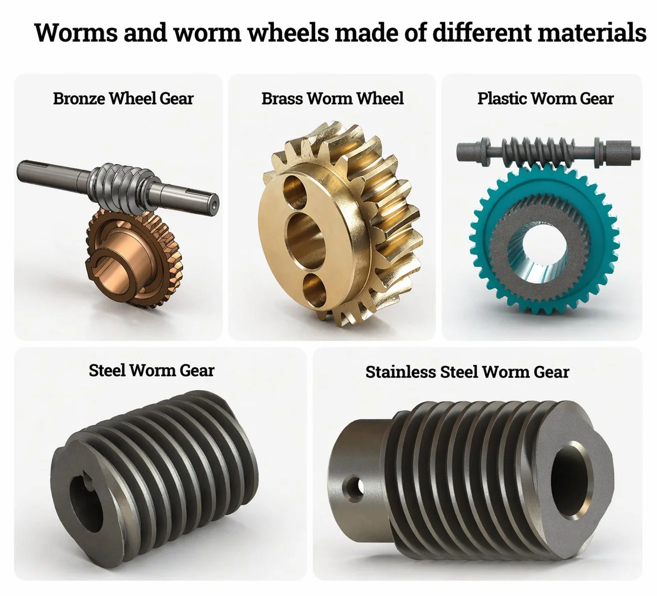
Worm: Case-hardened 16MnCr5 (HRC 58-62 surface, HRC 30-35 core). The hard case resists surface pitting; the softer core absorbs shock without brittle fracture.
Wheel: Gravity-cast phosphor bronze CuSn12Ni. Adequate for low to moderate cycle counts.
Finish: Worm ground Ra 0.8 µm; wheel hobbed Ra 1.6 µm.
Worm: Case-hardened 16MnCr5 (3m) or through-hardened 42CrMo4 HRC 28-34 (4m). Through-hardening gives uniform hardness — no case-core interface that can spall under repeated impact.
Wheel: Centrifugal-cast CuSn12Ni. Centrifugal casting produces denser, porosity-free material with 15 to 25 percent higher fatigue strength than gravity-cast.
Finish: Worm ground Ra 0.4 µm; wheel hobbed then run-in.
Worm: Zinc-plated case-hardened steel (inland port) or AISI 316L stainless (coastal/offshore).
Wheel: Aluminium bronze CuAl10Fe5Ni5 — no dezincification in salt spray, superior corrosion resistance to phosphor bronze. Slightly lower wear rate than CuSn12Ni at the cost of slightly higher friction coefficient.
Finish: Worm ground Ra 0.4 µm; all fasteners A4 stainless.
Three crane hoist worm gear pair specification cases
The three cases below span the FEM duty range from moderate factory crane to extreme port gantry. Each case demonstrates how the FEM duty group classification drives every specification parameter — from service factor and material through to inspection interval and replacement planning.
The specifications are real, the numbers are representative of actual procurement, and the lessons apply across the Korean, Japanese, and Southeast Asian crane manufacturing and maintenance markets.
Case 1 — Korean automotive plant: 8-tonne overhead crane, FEM 3m
A Korean automotive stamping plant specified worm gear pairs for four 8-tonne double-girder overhead cranes used for die changeover. Duty cycle: 15 to 20 lifts per shift, two shifts per day, 300 working days per year. Most lifts at 60 to 80 percent of SWL (stamping dies weigh 5 to 6.5 tonnes). FEM classification: 3m (heavy) based on annual operating hours approximately 2,500 and load spectrum concentrated above 60 percent SWL. Hoist drum diameter 350 mm, ratio 50:1, worm pair efficiency 44 percent. T_lift = (8,000 × 9.81 × 0.35) / (2 × 50 × 0.44) = 624 N·m. Emergency stop factor K_e = 2.5. T_shock = 1,560 N·m. SF (FEM 3m) = 2.25. T_required = 3,510 N·m. Specification: single-start, module 6, centre distance 160 mm, rated 3,800 N·m. Material: case-hardened 16MnCr5 worm ground Ra 0.4 µm, centrifugal-cast CuSn12Ni wheel. Separate spring-applied electromagnetic brake on the high-speed input shaft. Inspection: 6-month backlash measurement and contact pattern check. Service life achieved: 6.5 years average wheel life at 2-shift operation, exceeding the 5-year budget. Worm surviving two wheel changes.
Case 2 — Japanese port container handler: 40-tonne gantry, FEM 4m, marine corrosion
A Japanese port authority specified worm gear pairs for two 40-tonne ship-to-shore container gantry cranes operating in a coastal environment with direct salt spray exposure. FEM classification: 4m (very heavy) — 18 hours per day operation, 350 days per year, nearly all lifts at 80 to 100 percent SWL (loaded 20-foot containers weigh 24 to 30 tonnes). Hoist drum diameter 600 mm, ratio 60:1, worm pair efficiency 42 percent. T_lift = (40,000 × 9.81 × 0.6) / (2 × 60 × 0.42) = 4,672 N·m. K_e = 3.0 (heavy dynamic braking in container stacking). T_shock = 14,016 N·m. SF (FEM 4m) = 2.5. T_required = 35,040 N·m. This far exceeds single-pair capability — resolved by a dual worm gear pair arrangement (two pairs sharing the load through a common output gear train, each pair carrying half the torque at 17,520 N·m). Each pair: module 10, centre distance 250 mm, rated 18,000 N·m. Material: zinc-plated case-hardened worm (salt spray protection per ISO 12944 C4), aluminium bronze CuAl10Fe5Ni5 wheel (zero dezincification risk). All fasteners A4 stainless. Inspection: quarterly backlash measurement, monthly visual seal check, annual contact pattern verification. Browse heavy duty worm gear reducer options that include marine-grade corrosion protection for port and coastal crane applications.
Case 3 — Vietnamese construction site: 6-tonne tower crane, FEM 2m, cost-optimised
A Vietnamese construction equipment manufacturer specified worm gear pairs for a fleet of 30 tower cranes rated at 6-tonne SWL for residential building construction. FEM classification: 2m (moderate) — 8 to 10 lifts per hour during active construction, but only 200 to 250 working days per year, and most lifts well below SWL (concrete buckets at 2 to 3 tonnes, rebar bundles at 1 to 2 tonnes, full SWL lifts rare). T_lift at SWL: (6,000 × 9.81 × 0.30) / (2 × 40 × 0.46) = 480 N·m. K_e = 2.5. T_shock = 1,200 N·m. SF (FEM 2m) = 2.0. T_required = 2,400 N·m. Specification: single-start, module 5, centre distance 125 mm, rated 2,600 N·m. Material: standard case-hardened 16MnCr5 worm, gravity-cast CuSn12Ni wheel (cost-optimised — centrifugal-cast not required at 2m duty). Cost per pair: 380 USD. For a fleet of 30 cranes, the saving versus centrifugal-cast specification (estimated 580 USD per pair) was 6,000 USD — meaningful for a price-sensitive construction market. Inspection: annual, aligned with annual crane certification. Service life target: 4 years per wheel (matching the typical 4-year rental cycle of the crane). Achieved: 4.2 years average across the fleet, meeting the target with slight margin.
Foire aux questions
Q: Can a crane hoist worm gear pair ever use a 2-start worm?
Almost never for the hoist mechanism. A 2-start worm at typical q values produces a lead angle of 10 to 12 degrees — well above the friction angle and therefore non-locking. The load would fall if the brake failed. Some crane manufacturers use 2-start or 3-start worm pairs for the crane travel and cross-travel drives (horizontal motion), where there is no suspended load safety concern, and the higher efficiency reduces motor sizing. But the hoist drive — the mechanism that holds the load against gravity — is universally single-start with strong self-locking. This rule has no exceptions in any crane standard worldwide.
Q: How often should a crane hoist worm gear pair be inspected?
The FEM duty group table above specifies the interval: annual for 1Bm and 1Am, 6-monthly for 2m and 3m, quarterly for 4m, and monthly for 5m. The minimum inspection includes backlash measurement (compare to delivery certificate), visual seal check for grease weeping, and noise baseline comparison. For cranes above FEM 3m, add a contact pattern verification using marking compound at each 6-month interval. The contact pattern check is the only reliable method for detecting tooth flank pitting before it reaches the stage where backlash growth becomes measurable — giving typically 6 to 12 months of advance warning before replacement becomes urgent.
Q: What is the relationship between SWL and worm gear pair rated torque?
SWL (safe working load) is the maximum load the crane is permitted to lift. The worm gear pair rated torque must exceed the torque produced at SWL after applying the emergency stop shock factor and the FEM service factor. The typical relationship is T_rated (pair) = SWL × g × D_drum / (2 × i × η) × K_e × SF. For most overhead cranes with standard drum diameters and ratios, the required pair rated torque is roughly 4 to 6 times the steady-state lifting torque at SWL. This ratio explains why crane worm gear pairs appear “oversized” compared to conveyor or mixer applications at the same steady-state torque — the difference is entirely due to the emergency stop and FEM safety factors that crane applications demand.
Q: What brake type is required alongside the worm gear self-locking?
All crane hoist drives require a spring-applied, electrically-released disc or drum brake on the motor shaft (high-speed side). The brake engages automatically when electrical power is removed and provides holding torque independent of the worm gear self-locking. The brake is designed to hold the full SWL plus a safety margin (typically 1.5 to 2.0 times the static gravitational torque at the motor shaft). The worm gear self-locking and the mechanical brake form a two-layer holding system: if one fails, the other still prevents load fall. Some high-criticality cranes (FEM 4m and above) add a third layer — a ratchet pawl or overrunning clutch on the drum shaft — creating triple redundancy. This three-layer approach is typical in molten metal ladle cranes where a dropped load has catastrophic consequences.
Q: How do I determine the correct FEM duty group for a specific crane?
Two inputs are needed: the total number of hoisting cycles over the crane’s design life (typically 10 to 25 years) and the load spectrum class (what proportion of lifts are near SWL versus light loads). ISO 4301 and FEM booklet 2 provide the classification tables. As a practical shortcut: workshop cranes with fewer than 50 lifts per week are 1Bm; factory cranes with 50 to 200 lifts per week are 1Am to 2m; production cranes with 200 to 1,000 lifts per week are 3m; process cranes with continuous multi-shift operation are 4m to 5m. If the crane serves a production line and runs every working day, it is at least 2m regardless of how light the individual lifts are. Consult the crane manufacturer’s documentation for the official FEM classification — it should be stated on the crane data plate.
Q: Can I replace a crane hoist worm gear pair with a helical gear pair to improve efficiency?
Technically possible, but it changes the safety architecture fundamentally. A helical pair does not self-lock — the brake becomes the sole holding device. Most crane standards accept this (many modern high-speed cranes use helical pairs with high-performance brakes), but the maintenance regime changes: the brake must be inspected much more frequently. For existing cranes designed around worm gear self-locking, switching to helical without a safety review and brake upgrade is not recommended.
Crane and hoist worm gear pairs operate under the most rigorous safety framework of any industrial gear application. The FEM duty group classification connects the crane’s actual working life — its operating hours, load spectrum, and cycle count — to the service factor, material grade, and inspection interval of the worm gear pair. The emergency stop shock factor (2.5 to 3.0 times steady-state torque) is often the binding constraint that determines the minimum frame size — and specifying from steady-state lifting torque alone underrates the pair by a factor of 4 to 6. Material selection follows duty group: gravity-cast bronze for light duty, centrifugal-cast for heavy duty, aluminium bronze for marine environments. Inspection frequency compresses from annual to monthly as the duty group increases. The single universal rule across all duty groups is that crane hoist worm gear pairs must be single-start, strongly self-locking, and backed by a separate mechanical brake — geometric self-locking alone is necessary, the brake provides the redundancy that safety regulations demand.
For crane manufacturers and maintenance teams specifying hoist worm gear pairs, our engineering desk verifies the FEM duty group classification and runs the emergency stop shock calculation against your crane parameters. Standard catalogue phosphor bronze worm gear sets cover centre distances from 80 to 250 mm in single-start configurations with full DIN 3974 inspection documentation. Custom material pairings (aluminium bronze, stainless, through-hardened) and non-standard legacy replacement pairs available on 4 to 6 week lead times — submit a crane hoist drive specification with your SWL, drum diameter, and FEM group classification.
Specifying worm gear pairs for crane or hoist applications?
Send the crane SWL, hoist drum diameter, gear ratio, FEM duty group, and environment (indoor, outdoor, coastal, marine). We will calculate the emergency stop shock torque, recommend the correct FEM-grade material pairing, and quote both standard and custom options — typically within one working day.
edit by cxm


