Sonsuz Dişli Çarkların Üretimi — Diş Açma, Taşlama, Sertleştirme
Üretim sürecinin her aşamasında, bitmiş parçada bir iz kalır. Gelen ürün muayenesi sırasında bu izleri okumak, beş yıllık bir kullanım ömrünü beş aylık bir kullanım ömründen ayıran tedarik becerisidir.
Komple bir sonsuz dişli takımı altı üretim aşamasından geçer: malzeme hazırlığı, dişli ham maddesinin işlenmesi, diş profilini kesmek için frezeleme veya döndürme, çelik sonsuz dişliyi sertleştirmek için ısıl işlem, hassas yüzey işleme için taşlama ve kalite onayı için muayene. Her aşama, bitmiş parçada ölçülebilir kanıtlar bırakır - taşlama izleri, kasanın rengi, temas deseni, diş profili hatası. Ne arayacağını bilen bir alıcı, gelen mal muayenesi sırasında bu işaretlerin her birini aşama başına on beş dakikadan kısa sürede doğrulayabilir. Sadece frezelenmiş sonsuz dişliler DIN 7 ila DIN 8 doğruluk sınıfına ulaşır; taşlanmış sonsuz dişliler DIN 5 ila DIN 6'ya ulaşır. Tipik endüstriyel sonsuz dişliler için karbürlenmiş kasa derinliği 0,6 ila 1,2 milimetre arasındadır. Üst düzey üretim hatlarında taşlanmış diş profili hatası 0,005 milimetrenin altında kalır.
Alıcının üretim sürecini anlaması neden önemli?
Üretimi tamamlanmış bir sonsuz dişli takımı, her bir yüzeyinde üretim sürecinin izlerini taşır. Taşlama izleri, sonsuz dişlinin taşlanıp taşlanmadığını veya sadece frezelenip frezelenmediğini gösterir. Yüzey sertleştirmenin rengi ve derinliği, ısıl işlem profilini ve uygulandığı sıcaklığı gösterir. Mavileştirme testi altındaki diş temas deseni, montaj sırasında merkez mesafesinin doğru ayarlanıp ayarlanmadığını gösterir. Toplam bileşik hata, kesici takımın hassasiyet sınıfını ve onu üreten makinenin rijitliğini gösterir. Gelen malzeme muayenesi sırasında bu izleri okumak, her aşamanın ne ürettiğini ve hangi kanıtları arayacağınızı bildiğinizde dakikalar sürer.
Çoğu makale, dişli üretimini elli kelime ve bir stok fotoğrafla özetler: “sonsuz dişli frezelenir ve ardından sertleştirilir, dişli bronzdan frezelenir, montaj kontrol edilir ve sevk edilir.” Bu özet teknik olarak doğru olsa da operasyonel olarak işe yaramaz. Koreli bir ikinci kademe tedarikçi ile Japon birinci kademe tedarikçinin fiyatının 'ı arasında seçim yapması gereken satın alma mühendisi, fiyat farkını hangi üretim aşamalarının belirlediğini, hangi aşamaların daha düşük seviyeli ekipmanlarla güvenle çalıştırılabileceğini ve hangi aşamaların, altı ay sonra dişli aşınması şikayeti olarak ortaya çıkan kritik arıza noktaları olduğunu bilmek ister. Bu makale, alıcının bakış açısından altı aşamayı ele almaktadır.
Aşama 1 — Malzeme hazırlığı
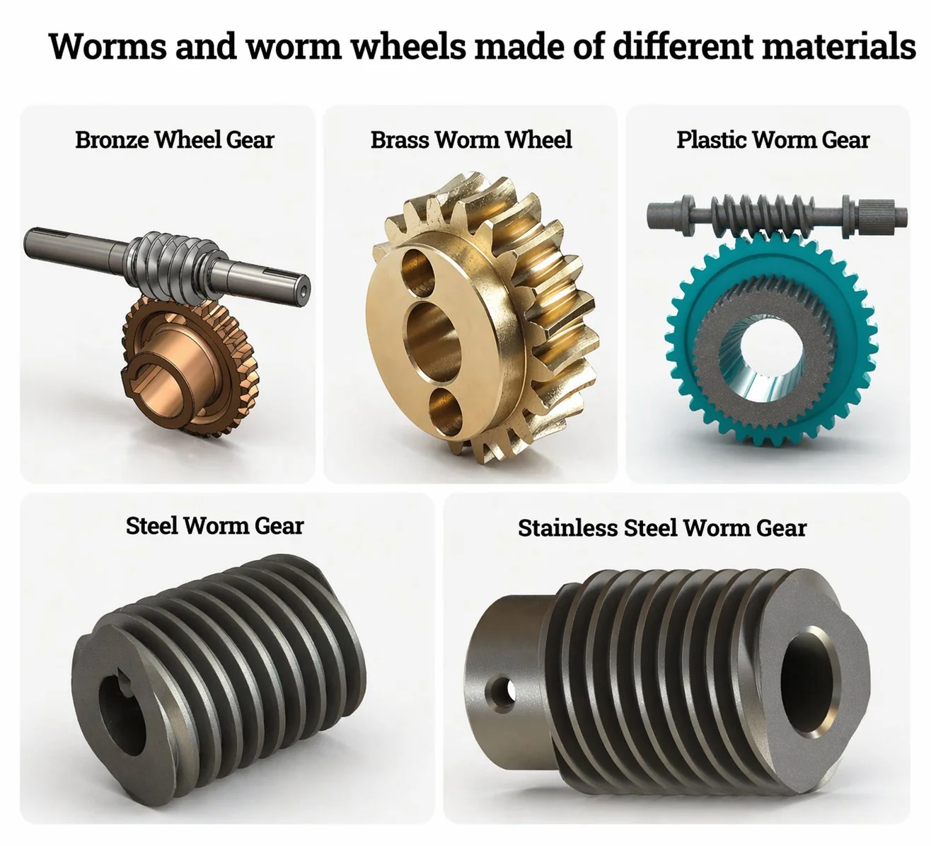
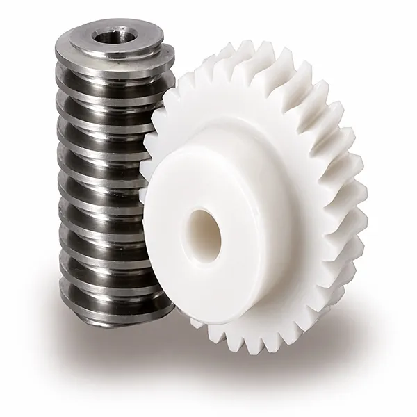
Sonsuz dişli milleri, dövme veya sıcak haddelenmiş çelik çubuktan başlar; tipik olarak endüstriyel tahrik sistemleri için JIS SCM415 yüzey sertleştirme çeliği veya 16MnCr5 eşdeğeri kullanılır. Sonsuz dişli çarkları ise dökme bronz levhalardan başlar: daha yüksek yük uygulamaları için fosfor bronz (CuSn12, JIS BC6) veya alüminyum bronz (CuAl10Fe3). Dökme bronz levhalar bazen doğrudan işlenir, bazen de daha büyük boyutlar için çelik bir göbeğe monte edilir.
Malzeme sertifikası, alıcının bu aşamada edinmesi gereken en önemli belgedir. Sertifika, kimyasal bileşimin standarda uygunluğunu belgelendirir ve partinin dökümhaneye veya çelik fabrikasına kadar izini sürer.
Bu aşamanın kontrol ettiği şeyler: Hem sonsuz vida hem de dişli çarkın temel malzeme özellikleri. Yanlış kalay içeriğiyle dökülmüş bir bronz dişli çark, sonraki aşamalarda geri kazanılamaz. Yanlış karbon içeriğine sahip bir çelik çubuk, düzgün bir şekilde yüzey sertleştirme işlemine tabi tutulamaz.
Alıcının doğrulayabileceği şeyler: JIS H 5111 (bronz) veya JIS G 4053 (çelik) standartlarına göre kimyasal bileşim testi yapılmış malzeme sertifikaları. Bronz jantın Brinell sertliğini kontrol edin — fosfor bronz için HB 80 ila 95, alüminyum bronz için HB 130 ila 170 arasında olmalıdır. Sertifika değerleriyle uyuşmaması, malzemenin değiştirildiğinin ilk işaretidir.
Aşama 2 — Dişli ham maddesinin işlenmesi
CNC torna tezgahları, çelik çubuğu sonsuz vida milinin dış çapına göre işler ve tekerlek boşluğunu jantın dış çapına ve iç çapına göre hazırlar. Bu aşamadaki tolerans disiplini, sonraki her aşamaya yansır: Dış çap doğruluğu düşük olan bir sonsuz vida mili, diş açıldıktan sonra düzgün çalışmaz ve iç çapı eşmerkezli olmayan bir tekerlek boşluğu, dişler ne kadar hassas kesilirse kesilsin, kullanım sırasında sallanan bir tekerlek üretir.
Modern CNC torna tezgahları, rutin üretimde sonsuz dişli milinin dış çap toleransını artı veya eksi 0,01 milimetreye kadar korur. Tekerlek boşluğu iç çapının dış çapa göre eşmerkezliliği genellikle 0,02 milimetre içinde kalır. Daha eski manuel veya yarı otomatik sonsuz dişli torna tezgahları, tek tek parçalarda eşdeğer kalite üretebilir, ancak üretim partisi genelinde tutarlılık azalır ve alıcı, toplu siparişlerde tutarlılık için ödeme yapar.
Bu aşamanın kontrol ettiği şeyler: Diş açma işleminden önce iş parçası ham maddelerinin boyutsal doğruluğu. Burada yapılan hatalar daha sonraki aşamalarda düzeltilemez.
Alıcının doğrulayabileceği şeyler: Yüzeylerin görsel muayenesi (titreşim izi yok, işleme adımı yok), tekerlek bir merkeze monte edilmiş haldeyken kadran göstergesi kullanılarak tekerlek üzerindeki delik eşmerkezliliğinin kontrolü. Kaliteli tedarikçiler, delik çapı, dış çap ve eşmerkezlilik ölçümlerini kapsayan bir boyut kontrol kaydı sunar.
3. Aşama — Sonsuz vida ve çark dişlerinin honlanması
Endüstriyel ölçekte sonsuz dişli imalatında hem sonsuz dişliler hem de sonsuz dişli çarkları için baskın diş açma işlemi, frezeleme (hobbing) yöntemidir. Frezeleme ucu, sonsuz dişli şeklinde helisel bir kesicidir ve iş parçasını frezeleme hızıyla senkronize olarak döndüren bir frezeleme makinesine monte edilmiştir. Frezeleme ucu ve iş parçası, sanki zaten birbirine geçmiş gibi birlikte yuvarlanır ve kesici kenarlar bu yuvarlanma hareketiyle diş profilini oluşturur. Aynı prensip, farklı frezeleme ucu geometrileri ve besleme stratejileriyle hem çelik sonsuz dişli hem de bronz dişli çark için geçerlidir.
Bu aşamanın kontrol ettiği şeyler: Diş profili geometrisi, hat hassasiyeti ve dişler arası mesafe. Freze bıçağının profili ve durumu doğrudan iş parçasına yansır. Aşınmış veya yeni bilenmiş bir freze bıçağı, işleme başlandıktan birkaç saat sonra profil hatası olarak kendini gösterir.
Alıcının doğrulayabileceği şeyler: Klingelnberg veya Zeiss dişli ölçüm merkezinden alınan diş profili muayene raporu. Rapor, DIN 3962 veya ISO 1328 limitlerine göre toplam profil hatası (Ff), hatve hatası (Fp) ve salınımı (Fr) gösterir. Ciddi üretim yapan tedarikçiler bu muayene kayıtlarını standart olarak tutarlar. Talep üzerine profil raporu sunamayan tedarikçiler genellikle DIN 8 doğruluk seviyesinin altında çalışmaktadır.
Aşama 4 — Isıl işlem (arıza açısından kritik aşama)
Çelik solucanlar, bronz tekerleğe karşı kayma temasından kaynaklanan aşınmaya dayanacak kadar sertlik kazandırmak için yüzey sertleştirme işlemine tabi tutulur. Kontrollü atmosferli bir fırında 900 ila 940 santigrat derece arasında 4 ila 8 saat süreyle karbonlama işlemi, 0,6 ila 1,2 milimetre derinliğinde karbonca zengin bir yüzey tabakası oluşturur; bu tabaka daha sonra su verilerek ve temperlenerek yüzey sertliği HRC 58 ila 62 arasına getirilirken, çekirdeğin sertliği HRC 30 ila 35 arasında kalır.
İndüksiyonla sertleştirme, orta yük uygulamaları için bir alternatiftir ve daha kısa işlem süresi ve daha düşük maliyetle 50 ila 55 HRC yüzey sertliği elde edilmesini sağlar.
Isıl işlem, sonsuz dişli üretiminde en kritik arıza aşamasıdır. Yetersiz sertleştirme derinliği, döngüsel yük altında sertleştirme yüzeyinin yumuşak çekirdeğe kadar yorulmasına ve aylar içinde çukurlaşmaya ve diş kırılmasına neden olur. Aşırı sertleştirme derinliği, diş yan yüzeyini kırılgan ve pul pul dökülmeye yatkın hale getirir. Yanlış temperleme sıcaklığı, sertleştirme yüzeyini çok sert ve kırılgan veya çok yumuşak ve aşınmaya yatkın hale getirir. Eğer fikstür, sonsuz dişli geometrisine uygun olarak tasarlanmamışsa, su verme sırasındaki deformasyon mükemmel şekilde işlenmiş bir sonsuz dişliyi mahvedebilir.
Bu aşamanın kontrol ettiği şeyler: Yüzey sertliği, kasa derinliği, çekirdek tokluğu ve boyutsal kararlılık. Isıl işlem hataları parçanın dışından görünmez; kullanım sırasında hızlandırılmış aşınma veya erken arıza olarak ortaya çıkar.
Alıcının doğrulayabileceği şeyler: Isıl işlem kaydı, işlem sıcaklığını, bekleme süresini, soğutma ortamını ve temperleme sıcaklığını göstermelidir. Yüzey sertliği, taşınabilir bir Rockwell veya Leeb sertlik ölçer ile kontrol edilmelidir (karbürlenmiş yüzey için HRC 58 ila 62 beklenir). Kesit alınmış bir numune üzerinde yüzey sertliği derinliğinin doğrulanması altın standarttır, ancak tahrip edici test gerektirir; bu da yalnızca ilk ürün muayenesi veya denetimi için pratiktir.
İki yıl önce Koreli bir otomotiv birinci kademe tedarikçisi denetiminde, garanti kapsamında geri çağırmayı tetikleyecek bir ısıl işlem kısayolu tespit edildi. Tedarikçi, fırın kapasitesini boşaltmak için karbonlama süresini 6 saatten 4 saate indirmişti. Yüzey sertliği, yüzey yeterince karbon emdiği için HRC 60'ta yine de başarılı bulundu. Ancak, kasa derinliği 0,9 milimetreden 0,55 milimetreye düştü; bu da yorulma ömrü için gereken minimum 0,7 milimetrenin çok altındaydı. Bu maliyet düşürme işlemi, her bir vida için yaklaşık 15 ABD doları tasarruf sağladı, tasarımda belirtilen 8 yıl yerine yaklaşık 18 ay sonra arıza verecekti ve sadece denetimde kesitli numune kasa derinliği ölçümü yapıldığı için tespit edildi. Kasa derinliği konusunda ilk ürün incelemesi, kesintinin tespit edilmemesi durumunda garanti riskine kıyasla ucuz bir sigorta niteliğindedir.
Aşama 5 — Taşlama ve son işlem
Isıl işlemden sonra, çelik sonsuz dişli mili, diş profilinde 0,05 ila 0,15 milimetre ve hatvede 0,02 ila 0,08 milimetre arasında boyutsal deformasyona uğrar.
DIN 5 veya DIN 6 hassasiyeti gerektiren uygulamalar için taşlama, bozulmayı ortadan kaldırır ve hassasiyeti geri kazandırır. Üst düzey üretim hatları, taşlamadan sonra diş profili hatasını 0,004 ila 0,005 milimetreye kadar düşürür; bu, yalnızca frezeleme yöntemiyle üretilen DIN 8 kalitesinden yirmi kat daha hassastır.
Diş taşlama makineleri, saniyede 45 ila 60 metre doğrusal hızda CBN veya korundum tekerlekler kullanarak, her geçişte 0,008 ila 0,02 milimetre derinlikte işlem yapar ve diş yan yüzeylerini Ra 0,4 mikrometre veya daha iyi bir yüzey pürüzlülüğüne kadar işler.
Bronz sonsuz dişli çarklar, frezeleme işleminden sonra genellikle taşlanmaz. Bronz, frezeleme işleminin doğrudan kabul edilebilir bir yüzey kalitesi (Ra 1,6 ila 3,2 mikrometre) üretmesini sağlayacak kadar yumuşaktır. Bazı hassas uygulamalar, dişli çarkın eşleşen sonsuz dişli çarka aşındırıcı macunla sürtülerek diş yüzeyinin ila 'inde cilalı bir temas deseni geliştirdiği bir alıştırma aşamasını içerir.
Alıcının taşlama kalitesine dair en güvenilir göstergesi, sonsuz vida dişinin yüzeyinin görsel olarak incelenmesidir. Sadece tırtıllı sonsuz vidalarda, diş yan yüzeyinde belirgin kesme yüzeyleri bulunur; bunlar, tırtıl kesme kenarlarının profili oluşturduğu küçük düz segmentlerdir. Taşlanmış sonsuz vidalarda ise, helis yönü boyunca uzanan karakteristik taşlama izleriyle pürüzsüz, sürekli diş yüzeyleri görülür. Bu fark, 10x büyüteçte çıplak gözle görülebilir ve iki yüzey işlemi arasında kesin bir ayrım vardır. Premium sonsuz dişli redüktörü Seçenekler arasında, daha yüksek doğruluk sınıfları için standart ekipman olarak toprak solucanları da bulunmaktadır.
Aşama 6 — Muayene ve kalite onayı
Son sonsuz dişli muayenesi, boyut doğrulaması, geometrik hassasiyet, yüzey kalitesi ve diş temas deseni gibi unsurları kapsar. Saygın sonsuz dişli üretim hatları, her bir üniteyi bir CMM (koordinat ölçüm makinesi) üzerinde boyut kontrolünden geçirir ve örnek bir alt kümeyi de Klingelnberg, Zeiss veya Gleason dişli ölçüm merkezinde dişliye özgü ölçümlerden geçirir. Sonuç olarak, her ünite veya üretim partisiyle birlikte taşınan bir sonsuz dişli boyut raporu ve bir diş profili raporu elde edilir.
Diş temas deseni kontrolü, sonsuz dişli çarkın dişine sürülen dişli işaretleme bileşiği (Prusya mavisi) kullanılarak yapılır ve ardından hafif yük altında çarka karşı döndürülür. Bileşik, temas bölgesindeki çark dişlerine geçer ve görünür bir iz bırakır. Doğru şekilde monte edilmiş bir sonsuz dişli çifti, çark dişinin yan yüzeyi boyunca merkezlenmiş, mevcut yan yüzey alanının ila 'ini kaplayan ve desenin bir dişten diğerine düzgün bir şekilde kaydığı bir temas deseni gösterir. Merkezden kaymış veya küçük boyutlu desenler, sevkiyat öncesinde düzeltilmesi gereken merkez mesafesi veya montaj hatalarını gösterir.
Üç gerçek üretim örneği
Vaka 1 — Kore otomotiv sektörünün 1. kademe tedarikçisinin PPAP denetimi
Koreli bir birinci kademe otomotiv tedarikçisi, elektrikli cam aktüatörü için yeni bir sonsuz dişli çifti için altı üretim aşamasının tamamını kapsayan eksiksiz bir PPAP (Profesyonel Üretim Onay Süreci) başvurusu gerçekleştirdi. Malzeme sertifikası, bronz çarkın ,8 kalay içeriğine sahip JIS BC6'dan döküldüğünü gösterdi (spesifikasyon ila - başarılı). Dişli tezgahı muayene kaydı, toplam 14 kez bileme işlemi yapılmış DIN 6 dişli tezgahını gösterdi (spesifikasyon 25'in altında - başarılı). Isıl işlem kaydı, 6 saat boyunca 920°C'de karbürleme, yağda soğutma ve 2 saat boyunca 180°C'de temperleme işlemlerini gösterdi. Kesit numunesi kasa derinliği: 0,85 milimetre (spesifikasyon 0,7 ila 1,0 - başarılı). Diş profili muayenesi: 0,008 milimetre profil hatası (DIN 7 spesifikasyonu - başarılı). Diş temas deseni: yan yüzey kaplaması merkezlenmiş - başarılı. Toplam PPAP döngüsü: 5 hafta. Tedarikçi başarılı bir şekilde onay aldı ve 4 yıldır bu müşteriye sıfır uygunsuzlukla sevkiyat yapıyor.
Vaka 2 — Japon takım tezgahı indeksleme hassasiyeti
Japon bir takım tezgahı üreticisi, 4 istasyonlu döner indeksleme cihazı için çiftli bir sonsuz vida ve dişli çark seti sipariş etti. Özellikler: Sonsuz vidada DIN 5 taşlama hassasiyet sınıfı, dişli çarkta elle taşlanmış temas deseni, artı veya eksi 5 yay saniyesi konumlandırma tekrarlanabilirliği. Üretim dizisi, CBN dişli çarkları saniyede 55 metre doğrusal hızda çalıştıran hassas bir diş taşlama makinesi (Klingelnberg WPG30) gerektiriyordu ve taşlama derinliği her geçişte 0,008 milimetre olarak tutuluyordu. Zeiss dişli ölçüm merkezinde yapılan son diş profili incelemesi, DIN 5 spesifikasyonu dahilinde 0,004 milimetre profil hatası verdi. Eşleşen sonsuz vida ile dişli çarkın elle taşlanması, temas deseni kapsamı sağladı. Bu tek set için teslim süresi: Malzeme tesliminden sevkiyata kadar 7 hafta (2 haftalık taşlama döngüsü dahil). Maliyet: Standart katalog eşdeğerinin yaklaşık 6 katı. Uygulama bu spesifikasyonu gerektiriyordu çünkü indeks hatası, müşteri tarafından üretilen parçalarda doğrudan işleme hatasına dönüşüyordu.
Vaka 3 — Vietnam'da maliyet odaklı katalog siparişi
Vietnamlı bir konveyör üreticisi, genel endüstriyel konveyörler için 50:1 oranlı katalog sonsuz dişli takımından 200 adet sipariş verdi. Özellikler: DIN 8 sadece frezeleme hassasiyeti, HRC 52 sertliğinde indüksiyonla sertleştirilmiş sonsuz dişli, standart fosfor bronz dişli. Daha düşük hassasiyet ve indüksiyonla sertleştirme, hassas taşlama aşaması olmadan tek bir frezeleme ve indüksiyonla sertleştirme hattında üretime olanak sağladı. Birim maliyet, eşdeğer bir DIN 6 taşlanmış sonsuz dişli spesifikasyonunun yaklaşık 'iydi. Müşteri, konveyör uygulamasının daha yüksek boşluğa tolerans göstermesi, orta düzeyde çalışma döngüsünde çalışması ve sermaye maliyetini baskın satın alma faktörü olarak değerlendirmesi nedeniyle daha düşük hassasiyeti tercih etti. Ders: Her uygulama DIN 5 kalitesine ihtiyaç duymaz. Spesifikasyonu uygulamaya uygun hale getirmek, uygulamanın kullanamayacağı hassasiyet için yüksek fiyatlar ödemekten kaçınmayı sağlar.
Sıkça sorulan sorular
S: Sonsuz vida dişlisi hassasiyeti için frezeleme ve taşlama arasında pratik olarak ne fark vardır?
Dişli açma işlemi, bitmiş bir sonsuz dişlide yaklaşık 0,02 ila 0,05 milimetre diş profili hatası üretir. Isıl işlemden sonra taşlama, bu hatayı 0,004 ila 0,008 milimetreye düşürerek bir mertebe daha hassasiyet sağlar. Hassasiyet farkı, tekerlek etrafındaki boşluk varyasyonunda, düşük hızlardaki hareketin düzgünlüğünde ve temas deseni kalitesinde kendini gösterir. Düzgün ve sabit yüklerle çalışan uygulamalar (konveyörler, mikserler) için sadece dişli açma işlemi yeterlidir. Sık sık yön değiştiren veya sessiz çalışma gerektiren uygulamalar (takım tezgahları, hassas indeksleyiciler) için taşlama, ila 'lık maliyet farkına değer.
S: Solucanımın doğru şekilde koruma altına alındığını nasıl anlarım?
İşlemin titizliğini artırmada üç gösterge vardır. Birincisi, taşınabilir Rockwell veya Leeb test cihazıyla yüzey sertliği ölçümü – karbürlenmiş yüzeyler için HRC 58 ila 62, indüksiyonla sertleştirilmiş yüzeyler için HRC 50 ila 55 olmalıdır. İkincisi, işlem sıcaklığı, bekleme süresi, su verme ve temperleme işlemlerini gösteren ısıl işlem kaydı. Üçüncüsü, tahrip edici ilk numunede kesitli numune ile sertleşme derinliği ölçümü – sertleştirilmiş tabakanın gerçek derinliğini ölçer (boyut ve yüke bağlı olarak endüstriyel vidalar için 0,6 ila 1,2 milimetre olmalıdır). Kesitli numune tahrip edicidir ve maliyeti artırır, ancak sertleşme derinliğini şüpheye yer vermeden doğrulamanın tek yoludur. Yüksek riskli siparişler için, seri üretime geçmeden önce tedarikçinin numunesinde ilk numune sertleşme derinliği doğrulaması talep edin.
S: Öğütme kapasitesi olmayan daha küçük bir tedarikçi otomatik olarak daha düşük kalite anlamına mı gelir?
Mutlaka öyle değil — uygulamaya bağlı. Sadece frezeleme yeteneğine sahip bir tedarikçi, genel endüstriyel sonsuz dişli talebinin çoğunu karşılayan DIN 7 ila DIN 8 hassasiyetiyle sınırlıdır. Konveyör, mikser veya vinç uygulaması için, sadece frezeleme kalitesi tamamen yeterlidir ve taşlama ekipmanı olmayan tedarikçinin genel giderleri ve fiyatı daha düşük olabilir. Uyumsuzluk, yüksek hassasiyetli bir uygulama (takım tezgahı, indeksleme, servo) için taşlama yeteneği olmayan bir tedarikçiden parça temin edildiğinde ortaya çıkar — sonuç, yüzeysel olarak doğru görünen ancak hassasiyet gereksinimini karşılayamayan parçalardır. Tedarikçi yeteneğini uygulama talebiyle eşleştirin, tersini değil.
S: Dönme hareketi nedir ve neden bazı sonsuz dişli millerinde diş açma işleminin yerini almaktadır?
Döndürme yöntemi, iş parçası etrafında dönen ve küçük talaşlar halinde malzeme çıkaran, içine yerleştirilmiş çok sayıda kesici uca sahip dairesel bir kesici kafa kullanır. Bu işlem, tek bir operasyonda hem kaba frezeleme hem de ince taşlamanın yerini alır. Avantajları: daha az işlem adımı, ısıl işlemden sonra diş taşlama gerektirmez, bitmiş yüzey pürüzlülüğü Ra 0,8 mikrometre veya daha iyi, DIN 6 ila DIN 7 aralığında boyutsal doğruluk. Döndürme yöntemi, azaltılmış çevrim süresinin daha yüksek ekipman maliyetini karşıladığı yüksek üretim hacimlerinde (yılda 5.000 adetten fazla) en uygun maliyetlidir. Daha küçük hacimler ve özel geometriler için, geleneksel frezeleme artı isteğe bağlı taşlama standart işlem dizisi olmaya devam etmektedir.
S: Tipik bir özel sonsuz dişli siparişi, çizimden teslimata kadar ne kadar sürer?
Sonsuz dişli çark malzemesi temini, standart alaşımlar için genellikle 1 ila 2 hafta sürer (özel bronzlar veya paslanmaz çelik için daha uzun). 2. Aşama ham işleme 3 ila 5 gün daha ekler. 3. Aşama ilk numunede frezeleme, freze ucu tasarımı ve üretimini içerir (özel bir freze ucu gerekiyorsa 2 ila 4 hafta, standart bir freze ucu uyuyorsa hemen). 4. Aşama ısıl işlem döngüleri, fırın bekleme süresine ek olarak 1 ila 2 gün sürer. 5. Aşama taşlama, taşlanmış özellikler için 3 ila 7 gün, sadece frezelenmiş için sıfır gün ekler. 6. Aşama muayenesi 2 ila 5 gün sürer. Standart özel sipariş için toplam döngü süresi: 5 ila 7 hafta. Yeni freze ucu tasarımı gerektiren ilk kez özel geometriler için: 8 ila 12 hafta. Mevcut takımlara karşı üretim hacmi yeniden siparişleri genellikle 4 ila 5 hafta sürer.
S: İlk ürün muayenesi, sonraki parti muayenelerinin kapsamadığı hangi konuları kapsar?
İlk ürün muayenesi (FAI), üretim kurulumunun belirtilen parçayı doğru şekilde ürettiğini doğrular; bu, üretilen parçaların çizime uygun olup olmadığını doğrulamaktan farklıdır. FAI tipik olarak tahribatlı testleri (kesitli kasa derinliği ölçümü, sökülmüş numunede tam yan yüzey muayenesi), her çizim boyutunda tam boyut ölçümünü, tam malzeme sertifikasyon izlemesini ve eşleşen parçaya karşı diş temas deseni testini içerir. Sonraki parti muayenesi, parçaların bir alt kümesindeki boyutların bir alt kümesini örnekler. FAI, sürecin parçayı üretebileceğini kanıtlar; parti muayenesi ise sürecin sapmadığını doğrular. Her ikisi de ciddi OEM tedariği için gereklidir ve yeni bir parçada FAI'nin atlanması, "parçalar iyi görünüyor ancak kullanımda arıza veriyor" şikayetlerinin tipik nedenidir.
S: Toplu sipariş vermeden önce bir tedarikçinin sonsuz dişli üretim kapasitesini nasıl denetleyebilirim?
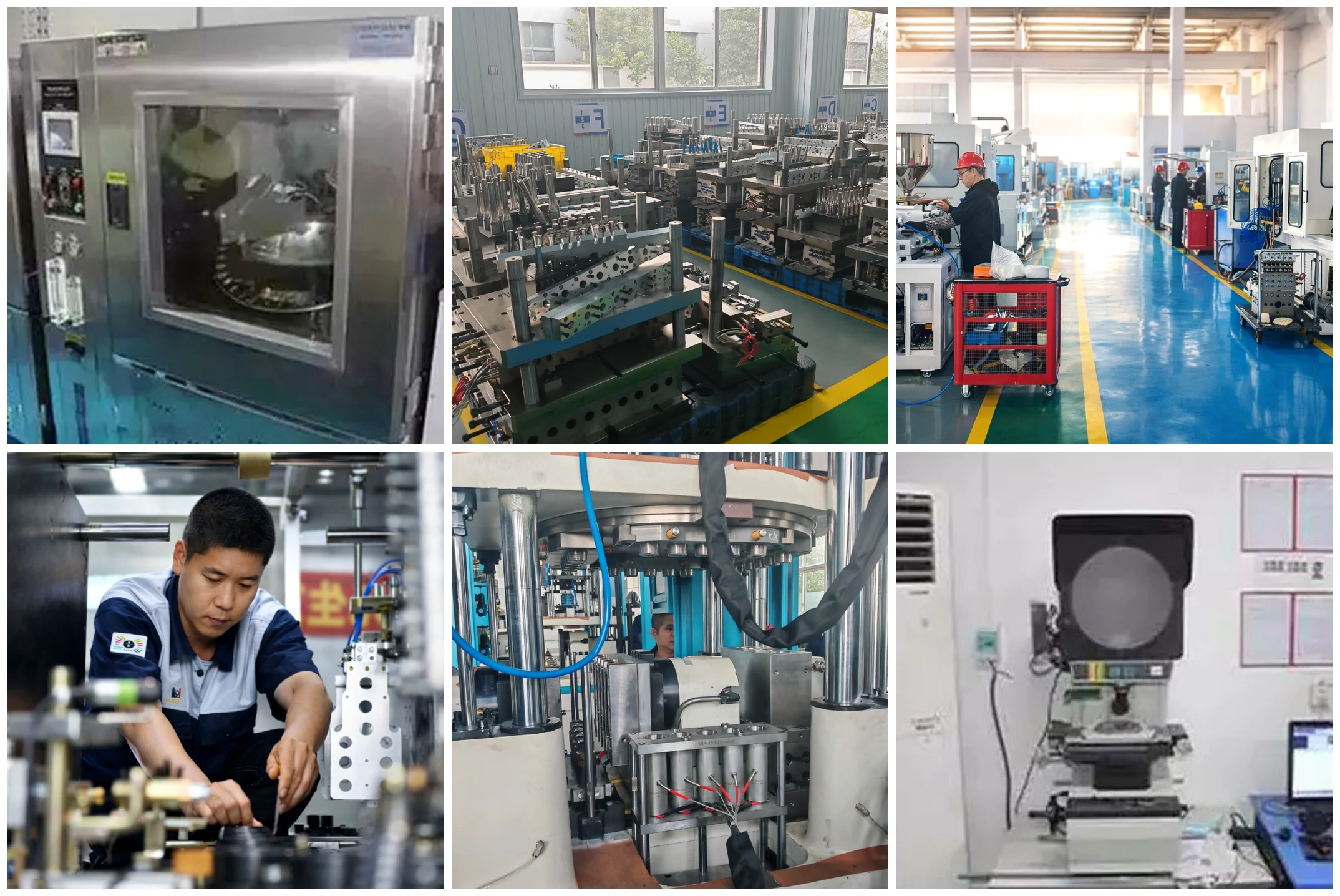
Faydalı bir sonsuz dişli tedarikçisi denetimi, yaklaşık yarım günlük yerinde incelemeyle altı alanı kapsar. Dişli frezeleme makinesi envanterini ve durumunu doğrulayın (üretici, yaş, son kalibrasyon). Isıl işlem fırını ve proses kayıtlarını inceleyin (karbürleme sıcaklık kontrolörleri, atmosfer izleme, soğutma tankı sıcaklık kayıtları). Taşlama yeteneğini kontrol edin (Klingelnberg veya eşdeğeri, bileme taşı envanteri, görsel inceleme için bitmiş sonsuz dişli örnekleri). Muayene odasında gezinin (CMM, dişli ölçüm merkezi, sertlik test cihazları, kalibrasyon kayıtları). Mevcut bir müşteri için bir tam FAI dosyasını inceleyerek dokümantasyon disiplinini doğrulayın. Mühendislik müdürüyle son 12 aydaki bir uygunsuzluk örneğini - nasıl tespit edildiğini, kök nedeninin nasıl belirlendiğini ve nasıl düzeltildiğini - 30 dakika boyunca görüşün. Bu altı alanlı denetim, tedarikçi yetenek endişelerinin yaklaşık 'ini yakalar.
Sonsuz dişli ve sonsuz çark imalatı, her biri bitmiş parçada ölçülebilir izler bırakan altı ayrı aşamadan oluşur. Her aşamanın neyi kontrol ettiğini ve hangi izlerin incelenmesi gerektiğini anlayan alıcı, her partinin tahrip edici bir şekilde sökülmesine gerek kalmadan tedarikçi kalitesini doğrulayabilir. 1. ve 2. aşamalar malzeme ve geometriyi belirler; 3. aşama diş profilini keser; 4. aşama çelik sertlik profilini ayarlar; 5. aşama gerektiğinde taşlama yoluyla hassasiyeti iyileştirir; 6. aşama sonucu onaylar. 4. aşamadaki ısıl işlem, en kritik arıza aşamasıdır çünkü buradaki hatalar parçanın dışından görünmezdir - ilk numunede kasa derinliği doğrulaması, "iyi görünüyor, 18 ay içinde arıza yapıyor" sonucuna karşı en ucuz sigortadır.
Koreli ve Japon OEM tasarım ve kalite ekiplerinin yeni bir sonsuz dişli tedarikçisini onaylaması sürecinde, mühendislik masamız ilk numune incelemesi, denetim incelemesi ve devam eden parti kalite onayı konularında destek sağlamaktadır. Standart katalog fosfor bronz ve sertleştirilmiş çelik sonsuz dişli takımları Malzeme sertifikaları, ısıl işlem kayıtları ve diş profili raporları da dahil olmak üzere eksiksiz dokümantasyon paketleriyle birlikte standart olarak gönderilir. Özel geometriler, seri üretime geçmeden önce FAI'nin kapı olarak kullanıldığı aynı altı aşamalı disiplini izler — lütfen talep edin. üretim süreci denetimi Ekibimiz, bir Kore iş günü içinde yetenek özetini ve örnek dokümantasyonu size iletecektir.
Yeni bir sonsuz dişli üreticisini nitelendirmek mi?
Başvuru şartlarını, gerekli doğruluk sınıfını ve beklenen yıllık hacmi gönderin. Size üretim kapasitesi özeti, örnek dokümantasyon paketi, FAI süreci zaman çizelgesi ve fiyatlandırma bilgilerini içeren bir e-posta göndereceğiz; bu bilgiler genellikle standart katalog özelliklerine göre bir Kore iş günü içinde iletilir.
Editör: Cxm


