Korea Ever-Power · Sovellussuunnitteluopas
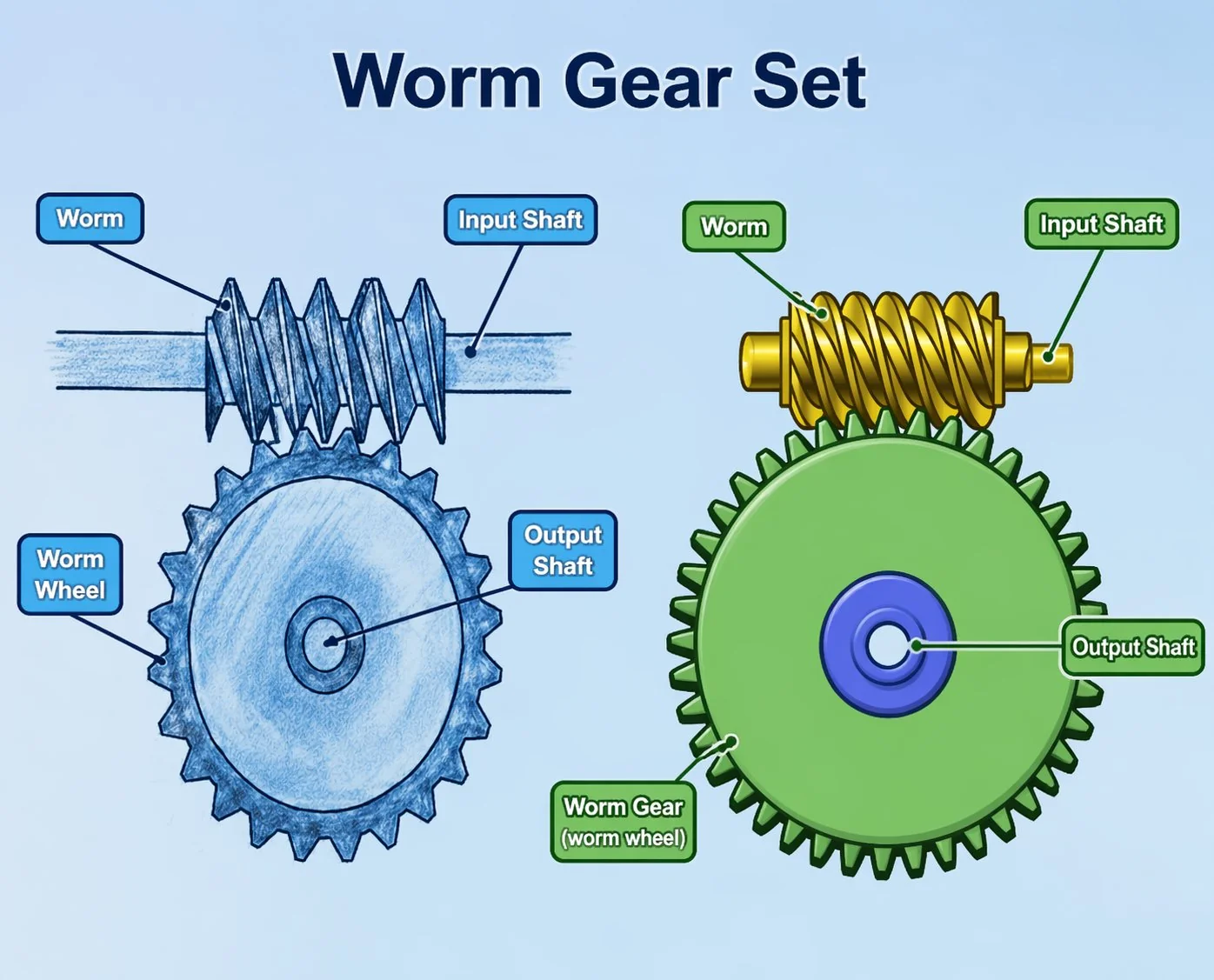
Worm and Worm Wheel for Milling Machine and Lathe Feed Drives
A milling cutter engages a steel workpiece at 2,000 N of tangential cutting force. The feed-direction component of that force — 400 to 800 N depending on the cutter geometry — pushes backward through the lead screw, through the worm gear pair, and tries to accelerate the table into the cutter. If the feed drive allows this acceleration, the tool digs deeper, the force increases, and the table accelerates further — a self-reinforcing crash that bends tools and damages machines. The self-locking worm gear pair is the mechanical barrier that prevents this feed-direction instability.
Milling machine and lathe feed drives use worm gear pairs for two simultaneous functions: controlled feed-rate reduction (converting motor speed to the slow, steady table or carriage movement during cutting) and self-locking safety (preventing cutting forces from back-driving the feed mechanism and pulling the workpiece into the tool). The cutting force feedback analysis traces how the tangential, radial, and axial components of cutting force resolve into a back-driving torque at the worm gear pair — and demonstrates that only self-locking worm geometry (single-start, lead angle below the friction angle) reliably absorbs this torque under all cutting conditions. Feed-rate accuracy depends on worm lead error: a 10 µm lead error per worm revolution produces a periodic feed-rate variation that appears as a surface finish waviness at the worm rotation frequency. Ground worms (Ra 0.3 to 0.4 µm, lead error below 5 µm) produce feed stability within plus or minus 1 percent; hobbed worms (Ra 1.6 µm, lead error 15 to 25 µm) produce plus or minus 3 to 5 percent variation visible as surface waviness on the finished part.
Why milling and lathe feed drives use worm gear pairs
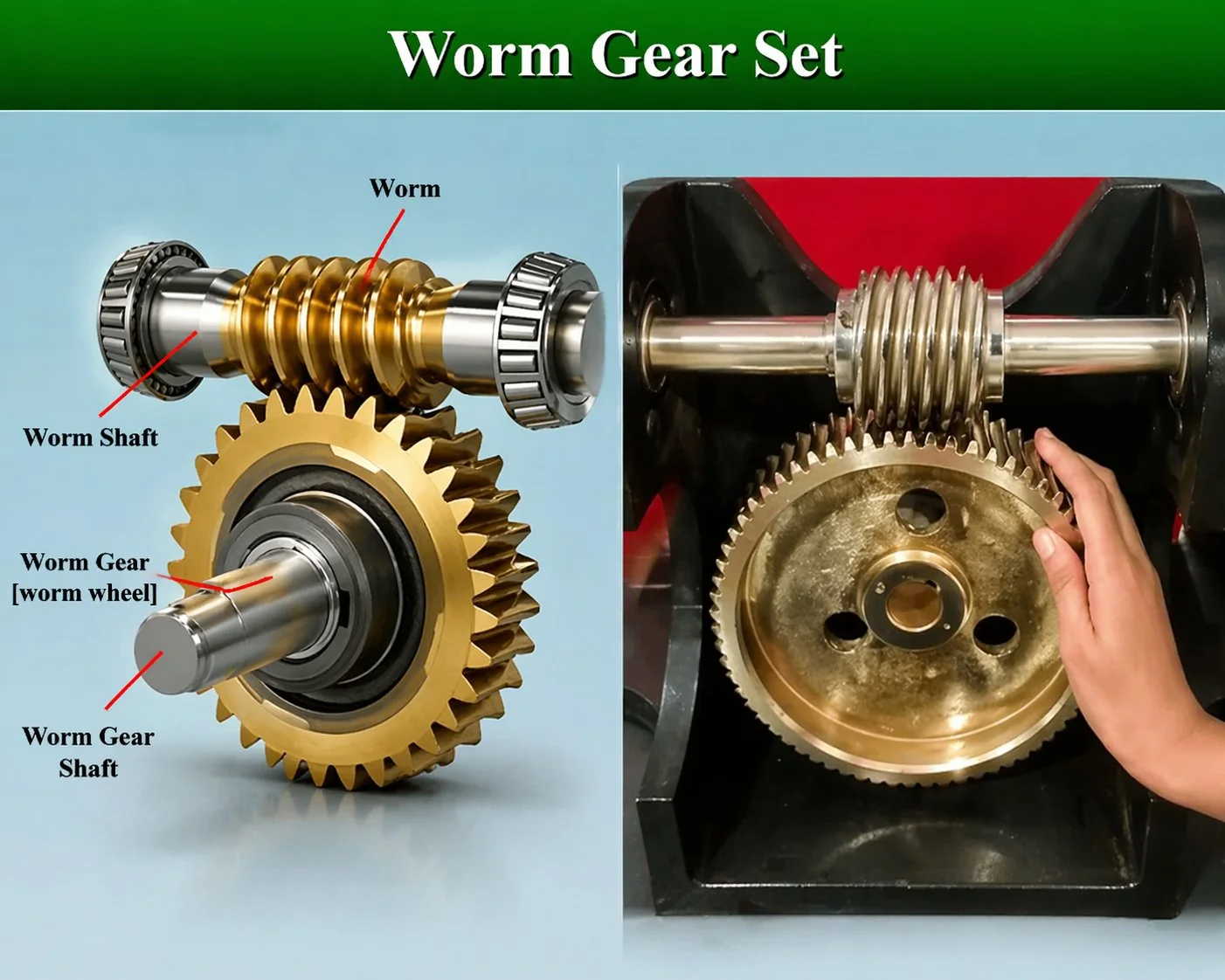
A machine tool feed drive converts motor rotation to slow, controlled linear movement of the worktable (milling) or cross-slide (lathe) during metal cutting. The feed rate — typically 10 to 500 mm per minute — determines the surface finish quality, the chip thickness, and the tool life. The worm gear pair sits between the feed motor and the lead screw, providing both the speed reduction and the critical self-locking safety function.
Unlike the rotary table application (Article A22) where the worm gear pair positions and holds, the feed drive pair moves continuously during cutting — making feed-rate consistency and cutting force absorption the primary specification parameters.
Self-locking absorbs the feed-direction cutting force component that tries to accelerate the workpiece into the cutter. Without self-locking, conventional or climb milling can produce a self-reinforcing feed acceleration that damages the tool, the workpiece, and the machine spindle — potentially injuring the operator.
The sliding contact of the worm and worm wheel produces inherently smoother rotation than spur gears — translating to a smoother feed rate with less periodic variation. Feed-rate smoothness directly determines surface finish quality: a 2 percent feed variation produces a 2 percent variation in chip thickness, visible as waviness on the machined surface.
A 40:1 worm gear pair converts a 1,450 RPM motor to 36 RPM at the lead screw — producing 180 mm/min feed rate through a 5 mm pitch lead screw. This single-stage ratio fits within the machine column or apron without extending the machine footprint. Spur gear trains need 3 to 4 stages for the same ratio.
Cutting force feedback analysis — how cutting forces try to back-drive the feed
During metal cutting, three orthogonal force components act on the workpiece at the cutting point. The component aligned with the feed direction is the critical one for the worm gear pair because it attempts to back-drive the feed mechanism through the lead screw.
The table below traces the force chain from cutting parameters through to the back-driving torque for three common machining scenarios — showing why self-locking is essential and why conventional (non-self-locking) gear drives are unsafe for milling feed applications.
The analysis shows that even heavy climb milling at 5,000 N tangential force produces only 10 N·m of back-driving torque at the worm gear pair — well within the self-locking capacity of any standard single-start pair (which resists back-driving torques up to the full output torque rating, typically 50 to 500 N·m for machine tool feed sizes). The worm gear pair absorbs the entire feed-direction cutting force without any strain. But the consequence of back-driving failure is severe: the workpiece accelerates into the cutter at the full lead screw lead rate, producing a crash that can break the tool, damage the spindle, and injure the operator. The self-locking margin is not marginal — it is designed to be overwhelming.
Feed rate accuracy — how worm lead error produces surface finish waviness
The feed rate determines the chip thickness and therefore the surface finish: a perfectly constant feed rate produces a perfectly uniform chip, which produces a smooth surface. A varying feed rate produces a varying chip thickness, which produces a wavy surface with a period corresponding to the variation frequency.
Lead error in the worm produces periodic feed variation. If the worm has a cumulative lead error of 15 µm over one revolution, the feed rate varies by 15 µm per revolution. At a 40:1 ratio with a 5 mm pitch lead screw, one worm revolution advances the table by 0.125 mm. A 15 µm error over 0.125 mm of travel represents a 12 percent instantaneous feed variation — producing a 12 percent chip thickness variation visible as periodic waviness with a wavelength of 0.125 mm on the finished surface. For finish machining where surface roughness Ra must be below 1.6 µm, this waviness is unacceptable.
Ground worms with lead error below 5 µm per revolution reduce the feed variation to below 4 percent — within the acceptable range for general machining (surface roughness Ra 1.6 to 3.2 µm). For precision finishing (Ra below 0.8 µm), lapped worms with lead error below 2 µm are specified. The lead error is not the same as the surface finish: a worm can have smooth Ra 0.4 µm surface finish but poor lead accuracy (10+ µm error) due to hobbing machine geometric errors. Lead error must be verified by direct measurement on a dedicated lead-testing instrument — not inferred from the surface roughness value.
A Korean knee mill manufacturer received field complaints about periodic surface waviness on the Y-axis (cross feed) during face milling. The waviness appeared as a regular pattern with a wavelength of approximately 0.13 mm — corresponding to the table advance per worm revolution (0.125 mm nominal at the feed rate used). Worm inspection revealed cumulative lead error of 18 µm over one revolution — within the supplier’s standard tolerance but producing 14 percent feed variation. The X-axis (longitudinal feed) showed no waviness — its worm had lead error of 4 µm (from a different production batch with tighter process control). Both worms were the same part number from the same supplier — the lead error was not controlled in the manufacturing specification, only the thread dimensions and surface finish. Resolution: the mill manufacturer added a lead error specification to the purchase order — maximum 6 µm cumulative per revolution, verified by inspection certificate. The supplier implemented 100 percent lead testing on an optical lead-checking instrument at an additional cost of 1.80 USD per worm. Surface waviness complaints reduced to zero across the following 12 months of production. Lesson: surface finish Ra and lead accuracy are independent parameters — specifying Ra alone does not guarantee feed accuracy. Add a maximum lead error per revolution to the purchase specification for any feed-drive worm.
Three machine tool feed drive worm gear pair cases
Case 1 — Korean knee mill manufacturer: 3-axis power feed, self-locking safety critical
A Korean vertical knee mill manufacturer specified worm gear pairs for the X, Y, and Z axis power feed units. Table size: 1,300 × 300 mm. Lead screw: 5 mm pitch, Acme thread. Motor per axis: 0.37 kW, 1,450 RPM. Worm gear pair: single-start, module 2, centre distance 40 mm, ratio 40:1. Output speed at lead screw: 36 RPM, producing 180 mm/min maximum feed rate. Self-locking: mandatory on all three axes — the Z-axis (vertical knee) carries the table, vise, and workpiece weight (up to 300 kg total), and a self-locking failure would allow the knee to drop under gravity. Lead error: below 6 µm per revolution (ground worm, Ra 0.4 µm). Material: case-hardened 20CrMnTi worm HRC 58, phosphor bronze CuSn12Ni wheel. Lubrication: ISO VG 68 machine oil, shared with the knee slide. Cost per pair: 42 USD. Cost for 3-axis set: 126 USD per mill. Annual production: 1,200 mills (3,600 worm gear pair sets). The 42 USD per pair is the most critical safety component on the mill — a self-locking failure on the Z-axis would allow a 300 kg table to free-fall onto the operator’s hands.
Case 2 — Japanese CNC lathe: cross-slide feed, servo-driven, surface finish critical
A Japanese CNC lathe manufacturer specified a worm gear pair for the cross-slide (X-axis) feed of a production turning centre machining automotive shaft components. The cross-slide feed determined the finished diameter tolerance (plus or minus 10 µm) and the surface roughness (Ra 0.8 µm required for bearing journal surfaces). Lead screw: 6 mm pitch ball screw (high efficiency for CNC servo control). Worm gear pair: single-start, module 1.5, centre distance 30 mm, ratio 30:1, ground Ra 0.3 µm, lead error below 3 µm per revolution. DIN accuracy class 5. Motor: 1 kW AC servo with 131,072-count encoder. Output torque at the worm wheel: 35 N·m (adequate for cross-slide friction plus cutting force feedback). Feed-rate variation from the worm: below 1 percent at all feed rates — producing surface waviness below 0.1 µm peak-to-valley (invisible at Ra 0.8 µm specification). Cost per pair: 125 USD. Browse worm gear for machine tool options designed for CNC lathe and milling machine feed drives.
Case 3 — Vietnamese radial drill press: power feed quill, cost-driven, hobbed acceptable
A Vietnamese machine tool manufacturer specified a worm gear pair for the power feed unit on a radial drill press quill drive. The drill press application was less demanding than milling: drilling produces axial thrust force (pushing the drill into the workpiece) rather than lateral feed force — so the back-driving risk was low (the thrust force acts along the quill axis, which is mechanically supported by the quill sleeve regardless of the worm gear pair). Self-locking was still specified for quill position hold (preventing gravity descent of the drill head when the feed motor stops). Worm gear pair: single-start, module 2, centre distance 35 mm, ratio 20:1. Hobbed worm, Ra 1.2 µm, lead error approximately 15 µm — acceptable for drilling where surface finish waviness is not a concern (hole quality is determined by drill geometry, not feed variation). Material: case-hardened carbon steel worm, sand-cast phosphor bronze wheel. Cost per pair: 18 USD. The case demonstrates that not all machine tool feed applications need ground worms — drilling, boring, and tapping are feed-rate-tolerant processes where hobbed worms at 3 to 5 times lower cost deliver equivalent functional results.
Usein kysytyt kysymykset
Q: Why is climb milling more dangerous without self-locking than conventional milling?
In climb (down) milling, the cutter teeth engage the maximum chip thickness first and exit at zero thickness. The initial engagement produces a strong force component that pulls the workpiece in the feed direction — toward the cutter. If the feed drive allows back-driving, this pull-in force accelerates the table, which increases the engagement depth, which increases the pull-in force — a positive feedback loop that ends in a violent crash within milliseconds. In conventional (up) milling, the teeth engage at zero thickness and exit at maximum — the force pushes the workpiece away from the cutter, which is self-correcting rather than self-reinforcing. Self-locking worm gear pairs make climb milling safe on manual mills — without them, climb milling is prohibited on machines with non-locking feed drives.
Q: Can CNC machines use ball screws instead of worm gear pairs for feed?
Modern CNC machines universally use ball screws for feed axes because ball screws provide higher efficiency (90+ percent versus 40 to 50 percent for worm gear pairs), lower friction, and zero backlash with preloaded nuts. Ball screws are not self-locking — the CNC servo motor and controller provide the position holding function electronically. The worm gear pair in CNC feed applications is typically used as a speed reduction stage between the servo motor and the ball screw when the motor speed range exceeds the ball screw critical speed — not as the primary feed mechanism. Manual machines (knee mills, engine lathes) retain worm gear pair feed drives because they lack servo motors and controllers that would provide electronic position holding — the self-locking worm gear pair is the safety mechanism that substitutes for electronic servo control.
Q: How do I verify the lead accuracy of a feed-drive worm?
Lead accuracy is measured on a dedicated thread-measuring instrument (such as a Mahr or Klingelnberg lead checker) that traces the helical path of the worm thread and compares it to the theoretical helix. The output is a lead deviation chart showing cumulative error in µm per revolution. The maximum cumulative error over one revolution is the specification parameter for feed-drive worms. This measurement cannot be performed with standard metrology tools (micrometers, CMMs do not trace the helical path). If your worm supplier does not have a lead-checking instrument, request that the worms be sent to a third-party metrology lab for lead verification — the test cost (5 to 15 USD per worm) is trivial against the production value of the machine tools that depend on the feed accuracy.
Q: What is the typical service life of a machine tool feed worm gear pair?
Manual machine tool feed worm gear pairs run intermittently — typically 500 to 1,500 hours per year of actual feed operation (the machine runs cutting cycles, not continuous feed). At this duty, the bronze wheel lasts 8 to 15 years. The hardened steel worm lasts the life of the machine (20 to 30 years). The life-limiting factor is usually backlash growth that degrades surface finish quality — plan wheel replacement when backlash exceeds 3 to 5 arcminutes (measurable as feed-direction play at the table). CNC feed worm gear pairs in production environments run 2,000 to 4,000 hours per year and may need wheel replacement every 5 to 8 years.
Q: Is a 2-start worm ever used in machine tool feed drives?
No — and this is an absolute rule for machine tool feed applications. A 2-start worm loses self-locking, which means the cutting force can back-drive the feed. This is not a performance trade-off — it is a safety hazard. The efficiency advantage of 2-start (higher feed motor efficiency, lower heat generation) does not compensate for the loss of the safety function. Every machine tool feed worm gear pair must be single-start, single-enveloping, with lead angle below the friction angle. There are no exceptions in any machine tool safety standard worldwide.
Milling machine and lathe feed drives use worm gear pairs as simultaneous speed reducers and safety devices — the self-locking property prevents cutting forces from back-driving the feed mechanism and causing tool pull-in crashes that damage machines and endanger operators. The cutting force feedback analysis traces how tangential cutting force resolves into back-driving torque at the worm gear pair, demonstrating that the self-locking margin is designed to be overwhelming rather than marginal. Feed-rate accuracy depends on worm lead error — a specification parameter independent of surface finish Ra that must be verified by dedicated lead-testing measurement. Ground worms with lead error below 5 µm produce surface finish suitable for precision machining; hobbed worms at 15+ µm are adequate only for drilling and roughing where feed variation does not affect part quality.
For machine tool manufacturers, our engineering desk provides feed-drive worm gear pairs with verified lead accuracy certificates. Standard catalogue precision worm gear sets include hobbed and ground feed-drive configurations from 30 to 80 mm centre distance with lead error documentation. Submit a machine tool feed specification with axis type, lead screw pitch, maximum cutting force, and surface finish requirement.
Specifying worm gear pairs for machine tool feed drives?
Send machine type, axis, lead screw pitch, maximum cutting force, surface finish target, and whether the application is manual (self-locking critical) or CNC (servo-controlled). We will calculate the back-driving torque and recommend the correct worm specification with lead accuracy verification.
Toimittaja: Cxm


