Korea Ever-Power · Application Engineering Guide
Tornillo sin fin y rueda helicoidal para actuadores de válvulas de compuertas y presas.
A flood control sluice gate on a Korean river holds 4 metres of water head — 40 kN of hydrostatic force per metre of gate width — against a worm gear pair that may sit motionless for 11 months between operations. When the monsoon arrives and the gate must open, the worm gear pair must overcome months of static friction, corrosion bonding, and silt accumulation on the first command. Failure to open is not a maintenance issue — it is a flood event.
Sluice gates, dam valves, penstock actuators, and flood control gates use worm gear pairs because no other gear type combines self-locking water-pressure holding with hand-wheel manual override capability. The submersion and flood exposure protocol classifies actuator installations into four levels — splash zone, intermittent flood, permanent submersion, and pressurised submersion — and maps each to the required IP rating, corrosion protection, seal type, and cathodic protection specification. Self-locking holds the gate at any position against water pressure without a separate lock mechanism. Emergency manual override via hand-wheel is mandatory for all dam and flood gates because power failure during a flood event is the most probable scenario requiring gate operation. Corrosion severity ranges from mild (fresh-water irrigation canal) through moderate (brackish estuary) to severe (seawater coastal defence) — requiring material progression from zinc-plated steel to 316L stainless to duplex stainless with sacrificial anode protection.
Why sluice gates and dam valves use worm gear actuators
Water control infrastructure — irrigation dams, flood gates, river weirs, reservoir outlets, and tidal barriers — operates at the intersection of high torque (moving heavy steel gates against water pressure), infrequent duty (some gates operate only during seasonal floods), and absolute reliability (failure during a flood can cause loss of life and property). The worm gear pair meets all three requirements through self-locking position hold, high single-stage ratio for manual override, and the mechanical simplicity that survives years of dormancy.
Three properties make the worm and worm wheel the standard for water gate actuators across every continent and every climate.
A partially open sluice gate experiences asymmetric water pressure trying to force it fully open or fully closed (depending on gate geometry). Self-locking holds the gate at any intermediate position against this pressure — enabling precise flow control without a separate hydraulic lock or mechanical latch.
When the electric motor fails (common during flood events when power infrastructure is damaged), an operator can drive the same worm gear pair via a hand-wheel. The high ratio (40:1 to 100:1) translates the operator’s hand-wheel torque into the thousands of newton-metres needed to move a heavy gate against water pressure.
Some flood gates sit closed for 6 to 11 months between operating seasons. The worm gear pair must survive this dormancy — resisting corrosion, silt intrusion, and static friction bonding — and operate reliably on the first command when the flood arrives. No other gear type is tested against months-long dormancy as a routine specification.
Submersion and flood exposure protocol — from installation level to protection specification
The defining specification challenge for sluice gate worm gear pairs is water exposure — not just splash or rain (which gate operators in Article A09 also face), but partial or complete submersion during normal operation or flood events. The submersion protocol classifies actuator installations by their exposure to water and maps each level to the required protection.
The cost escalation across submersion levels is dramatic: an S1 splash-zone actuator worm gear pair may cost 400 to 800 USD; an S4 pressurised-submersion pair with duplex stainless and pressure-balanced seals may cost 8,000 to 15,000 USD. The specification must match the actual installation submersion level — over-specifying wastes infrastructure budget; under-specifying produces corrosion failure within 2 to 5 years in a location that may require diver access or reservoir drawdown for replacement.
Emergency manual override — hand-wheel operation during power failure
The most probable time a flood gate must operate is during a flood. The most probable time power fails is during a flood — when floodwater damages electrical infrastructure upstream. Manual override is therefore not an emergency backup for rare events; it is the expected operating mode during the most critical moments of the gate’s service life.
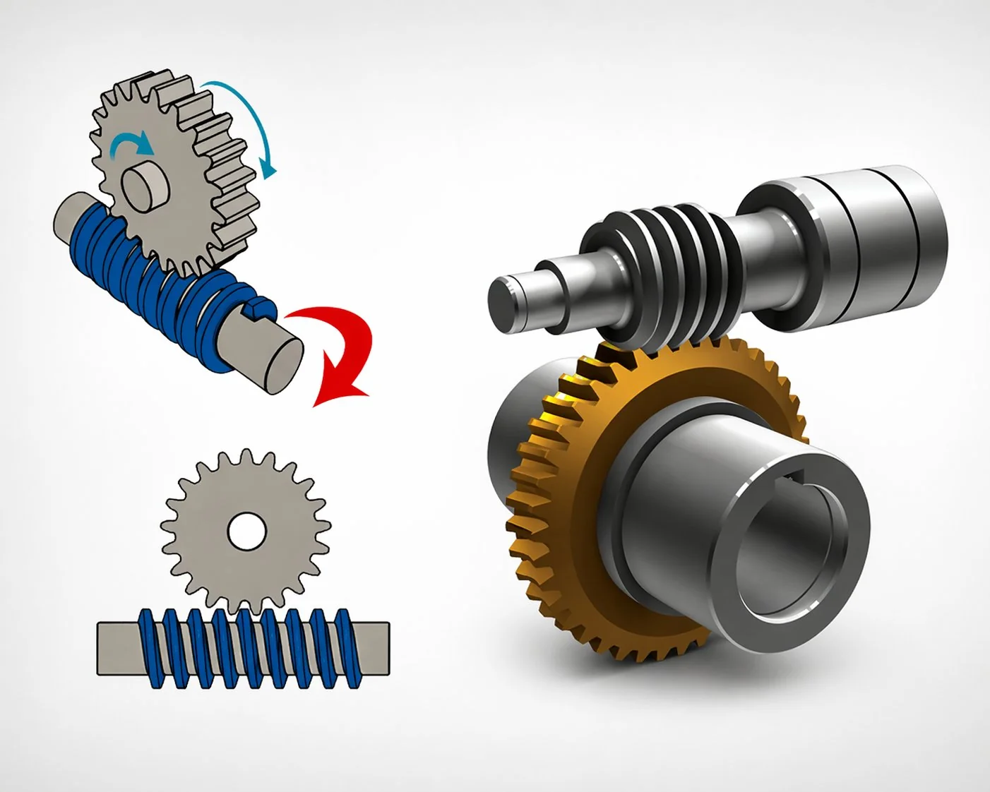
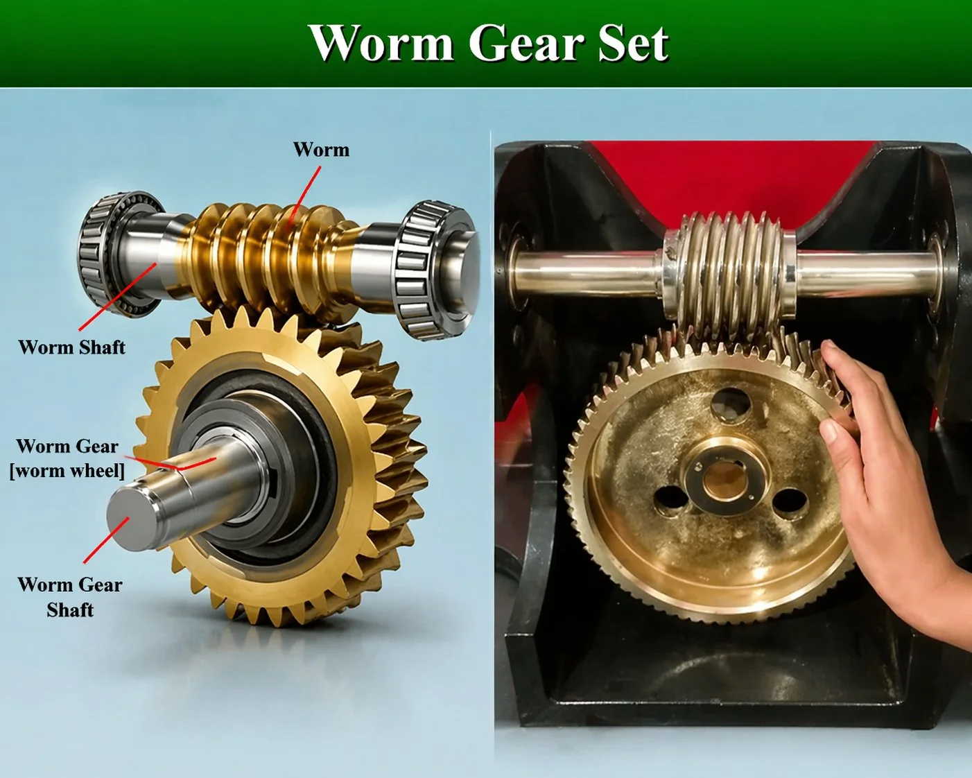
How manual override works with the worm gear pair. The actuator has two input paths to the same worm shaft: the electric motor (normal operation) and a hand-wheel with a declutch mechanism (manual override). When the operator engages the hand-wheel, the motor is declutched and the operator rotates the worm directly via the hand-wheel. The high worm gear ratio (typically 60:1 to 100:1 for gate actuators) multiplies the operator’s hand-wheel torque — an operator applying 250 N of force on a 400 mm hand-wheel (100 N·m input) through a 80:1 worm gear pair delivers 80 × 100 × 0.40 = 3,200 N·m at the gate stem. This is sufficient to move most irrigation and flood gates against normal water head.
Gate travel time under manual operation. A gate that opens in 2 minutes under motor drive may require 15 to 30 minutes of continuous hand-wheel cranking. For flood gates where rapid opening is critical, some installations provide a portable generator connection (bypassing the manual override) or a battery-backed motor drive as an intermediate solution between full manual and full mains power.
A Korean river management authority tested manual override on 22 flood gate actuators during the pre-monsoon annual inspection. All 22 gates had been closed for 8 to 10 months since the previous monsoon season. Result: 4 of 22 actuators failed to respond to the hand-wheel — the worm gear pair was seized. Investigation found that water had penetrated the IP66-rated housing through degraded lip seals during winter freeze-thaw cycles (ice expansion damaged the seal lip edge). Inside the housing, the grease had emulsified and the steel worm had developed surface corrosion bonding with the bronze wheel at the contact point. The seizure was not a catastrophic failure — a penetrating oil soak and manual rocking freed all 4 pairs within 2 hours. But the 2-hour delay on a flood gate during an actual flood event would be unacceptable. Corrective action: upgrade all 22 actuators from IP66 to IP67 (submersion-rated seals for the S2 intermittent flood level — appropriate for actuators that experience annual flood submersion), and implement a quarterly hand-wheel rotation exercise programme (4 full turns in each direction) to prevent corrosion bonding during dormancy periods. The exercise programme costs zero in parts and 15 minutes per gate per quarter — 22 gates × 15 min × 4 quarters = 22 hours of labour per year to guarantee flood-readiness of 22 gates. Lesson: dormant worm gear pairs in water infrastructure must be exercised regularly to prevent corrosion bonding — the self-locking property that holds the gate also prevents manual freeing if the contact surfaces bond during extended static periods.
Corrosion resistance — fresh water, brackish estuary, and seawater
Corrosion rate: 0.02-0.05 mm/year on carbon steel.
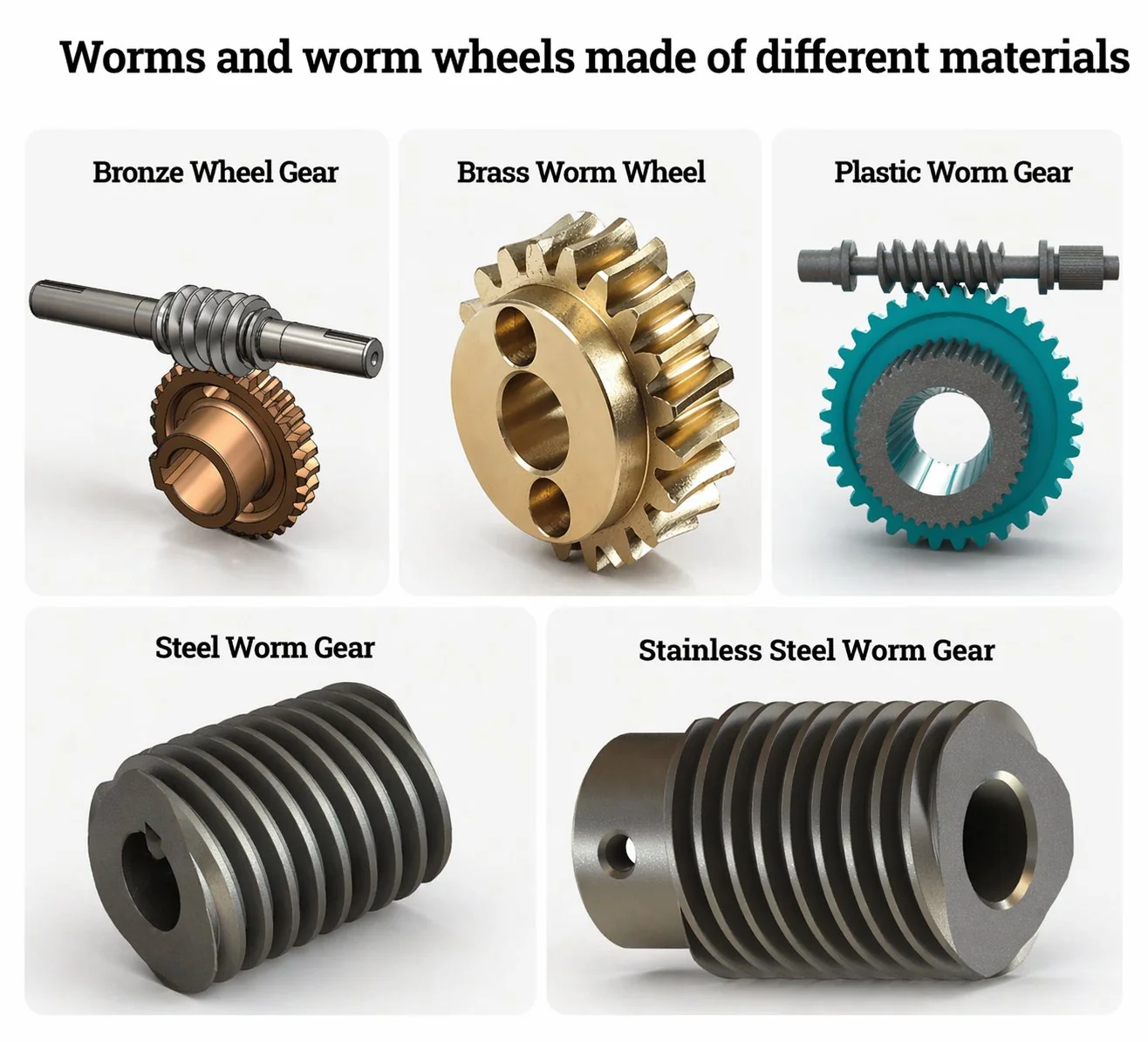
Worm: Hot-dip galvanised or 304 stainless.
Wheel: Phosphor bronze CuSn12Ni (standard — no dezincification risk in fresh water).
Life: 20-30 years at S1/S2 exposure.
Corrosion rate: 0.1-0.3 mm/year on carbon steel.
Worm: 316L stainless steel (molybdenum content resists chloride pitting).
Wheel: Aluminium bronze CuAl10Fe5Ni5 (no dezincification in chloride water).
Life: 15-25 years with cathodic protection.
Corrosion rate: 0.3-1.0 mm/year on carbon steel.
Worm: 2205 duplex stainless or Monel 400.
Wheel: Nickel aluminium bronze NAB (MIL-spec marine alloy).
Life: 15-20 years with impressed current cathodic protection system.
Three sluice gate and dam valve worm gear pair cases
Case 1 — Korean irrigation dam: 3 m wide sluice, S1 splash zone, manual override
A Korean agricultural water management authority specified worm gear pairs for 6 sluice gates on an irrigation dam supplying rice paddy fields. Gate width: 3 metres. Gate height: 2.5 metres. Water head at maximum reservoir level: 3.2 metres. Hydrostatic force on gate: 3.0 × 2.5 × 0.5 × 9,810 × 3.2 = 117,720 N. Gate stem thrust: approximately 85,000 N (including friction). Actuator output torque at stem nut: 4,200 N·m. Worm gear pair: single-start, module 6, centre distance 160 mm, ratio 60:1. Motor: 2.2 kW three-phase. Manual override: 500 mm hand-wheel (input torque 125 N·m at 250 N hand force, output 125 × 60 × 0.42 = 3,150 N·m — sufficient for normal water head but marginal at maximum head). Submersion level: S1 (actuator mounted on the dam crest, above maximum water level). Material: hot-dip galvanised worm, phosphor bronze wheel. Seal: IP66, double lip. Paint: ISO 12944 C3 (mild rural atmosphere). Cost per actuator worm gear pair: 580 USD. Quarterly exercise programme: 4 turns in each direction to prevent dormancy bonding. Service life target: 25 years.
Case 2 — Japanese typhoon flood gate: 6 m wide, S2 intermittent flood, battery backup
A Japanese prefectural flood management agency specified worm gear pairs for 4 flood gates on an urban river in a typhoon-prone coastal city. Gate width: 6 metres. Maximum water head during typhoon surge: 5.5 metres. Gate stem thrust: 220,000 N. Actuator output torque: 12,800 N·m. The actuator pedestal was 1.2 metres above normal water level but submerged during typhoon surge events (S2 — intermittent flood, submersion duration 6 to 24 hours per event, 2 to 4 events per year). Worm gear pair: single-start, module 8, centre distance 200 mm, ratio 80:1. Material: 316L stainless worm, aluminium bronze CuAl10Fe5Ni5 wheel (brackish water — river mouth, tidal influence). Seal: IP67, PTFE lip plus labyrinth. Paint: ISO 12944 C4-H (coastal). Cathodic protection: zinc sacrificial anodes bolted to the housing exterior (replaced every 5 years). Manual override: 600 mm hand-wheel. Additionally: 48 V battery-backed motor drive for emergency operation during power failure — providing 3 complete open-close cycles on a full battery charge. Cost per actuator worm gear pair: 3,200 USD. Battery backup system: 4,500 USD per gate. Browse worm gear actuator options for flood gate and water infrastructure applications.
Case 3 — Vietnamese Mekong Delta sluice: 2 m wide, S2 tidal brackish, cost-constrained
A Vietnamese provincial water authority specified worm gear pairs for 12 small sluice gates controlling salt-water intrusion into agricultural canals in the Mekong Delta. Gate width: 2 metres. Water head: 1.8 metres (tidal differential). Gate stem thrust: 28,000 N. Actuator output torque: 1,400 N·m. Submersion: S2 (tidally submerged twice daily for 2 to 4 hours during spring tides). The brackish water (salinity 5 to 15 parts per thousand) required corrosion-resistant materials, but the provincial budget constrained the specification. Worm gear pair: single-start, module 5, centre distance 125 mm, ratio 50:1. Material: 304 stainless worm (less corrosion-resistant than 316L but adequate at moderate salinity and significantly cheaper), phosphor bronze wheel (acceptable for brackish at this salinity level — dezincification risk is low below 15 ppt). Seal: IP67, EPDM lip with labyrinth. Cathodic protection: zinc sacrificial anodes (replaced annually due to high dissolution rate in brackish water). Manual override: 400 mm hand-wheel. Cost per pair: 720 USD. Life target: 15 years with annual anode replacement (18 USD per anode set). Annual inspection: hand-wheel exercise (quarterly), seal condition (annually), anode consumption (annually). Total 15-year maintenance budget per gate for the worm gear system: approximately 540 USD (anodes + labour) — roughly 75 percent of the initial pair cost.
Preguntas frecuentes
Q: How do I prevent a dormant sluice gate worm gear pair from seizing?
Implement a quarterly exercise programme: rotate the hand-wheel 4 full turns in each direction (open then close) to break any corrosion bonding at the tooth contact surfaces. Apply a thin film of anti-seize compound (zinc-based for fresh water, nickel-based for brackish/seawater) to the accessible worm thread after each exercise. For gates that cannot be exercised (permanently submerged S3/S4), specify marine-grade anti-seize compound in the original grease fill and increase the cathodic protection current density to suppress the electrochemical corrosion that causes bonding. The exercise programme is the single most effective preventive maintenance action for water gate worm gear pairs — and costs only labour time.
Q: What torque does the hand-wheel manual override produce?
T_output = F_hand × R_wheel × i × η. For a typical installation: F_hand = 250 N (one-hand sustained effort), R_wheel = 0.25 m (500 mm diameter wheel), i = 80 (worm gear ratio), η = 0.40 (single-start worm pair efficiency in the driving direction). T_output = 250 × 0.25 × 80 × 0.40 = 2,000 N·m. For a two-person hand-wheel (extending the wheel radius or using a portable handle extension), multiply by the force ratio. Most irrigation gates require 1,500 to 5,000 N·m at the stem — achievable with standard hand-wheel operation. Large flood gates requiring above 10,000 N·m may need a portable gearbox multiplier (2:1 to 5:1 hand-operated reducer between the hand-wheel and the worm shaft) or battery-backed motor drive for practical manual operation within a reasonable time.
Q: How long does cathodic protection extend the worm gear pair service life?
Properly maintained cathodic protection (sacrificial anodes or impressed current) effectively stops electrochemical corrosion — extending the worm gear pair life from 5 to 10 years (unprotected in brackish/seawater) to 15 to 25 years. The protection works only while the anodes have remaining material (sacrificial) or the power supply is functioning (impressed current). Sacrificial zinc anodes in brackish water typically last 3 to 5 years before replacement; in seawater, 2 to 3 years. The annual cost of anode replacement (15 to 50 USD per anode set) is negligible against the cost of worm gear pair replacement (700 to 15,000 USD depending on submersion level and material). Cathodic protection is the single highest-ROI maintenance investment for submerged water gate worm gear pairs.
Q: Can a sluice gate worm gear pair use a multi-start worm for faster gate travel?
A multi-start worm would provide faster gate travel (higher output speed for the same motor speed) but would lose self-locking — the water pressure would back-drive the gate open or closed when the motor stops. Since self-locking position hold is the primary reason for using a worm gear pair in gate actuators, multi-start configurations are not used. Faster gate travel is achieved by increasing the motor speed (using a 4-pole motor instead of 6-pole, or adding VFD speed boost) rather than changing the worm geometry. The self-locking constraint means all sluice gate worm gear pairs are single-start — this is a universal rule with no exceptions in water infrastructure standards worldwide.
Q: What lubricant should be used in a submerged sluice gate worm gear pair?
For S1 and S2 installations (splash and intermittent submersion): marine-grade lithium complex grease with corrosion inhibitor package, NLGI 2. Re-grease annually through a grease fitting. For S3 and S4 installations (permanent and pressurised submersion): the housing is oil-filled rather than greased — oil provides better corrosion protection for submerged surfaces and allows pressure equalisation without the air gaps that grease packing leaves. The oil specification is ISO VG 460 or 680 synthetic PAG with anti-corrosion and anti-wear additive packages verified for the specific water chemistry (fresh, brackish, or seawater). Oil change is performed during dewatered maintenance windows (typically every 5 to 10 years for reservoir gates, annually for tidal gates).
Sluice gate and dam valve worm gear pairs operate at the extreme end of the environmental exposure spectrum — from splash-zone irrigation gates to permanently submerged reservoir outlets and pressurised hydropower penstocks. The submersion and flood exposure protocol classifies installations into four levels and maps each to the IP rating, corrosion protection, seal type, and cathodic protection that determine both the initial cost and the multi-decade service life. Emergency manual override via hand-wheel is not a convenience feature — it is the expected operating mode during flood events when power infrastructure is most likely to fail. Dormancy management through quarterly hand-wheel exercise prevents the corrosion bonding that turns a functional worm gear pair into a seized mechanism at the worst possible moment. For water infrastructure operators, the worm gear pair is the mechanical heart of the gate actuator — and its specification, protection, and maintenance determine whether the gate opens when the flood arrives.
For water infrastructure agencies and gate actuator manufacturers, our engineering desk classifies the submersion level and recommends the material, seal, and cathodic protection package. Standard catalogue heavy-duty worm gear sets cover gate actuator sizes from 100 to 250 mm centre distance with S1 through S3 protection packages. Submit a sluice gate actuator specification with gate dimensions, water head, water type, and installation submersion level.
Specifying worm gear pairs for sluice gates or dam valves?
Send gate dimensions, water head, water type (fresh, brackish, seawater), installation submersion level, and whether manual override or battery backup is required. We will classify the submersion protocol and recommend the material, seal, and cathodic protection package.
Editor: Cxm


