Korea Ever-Power · คู่มือวิศวกรรมการใช้งาน
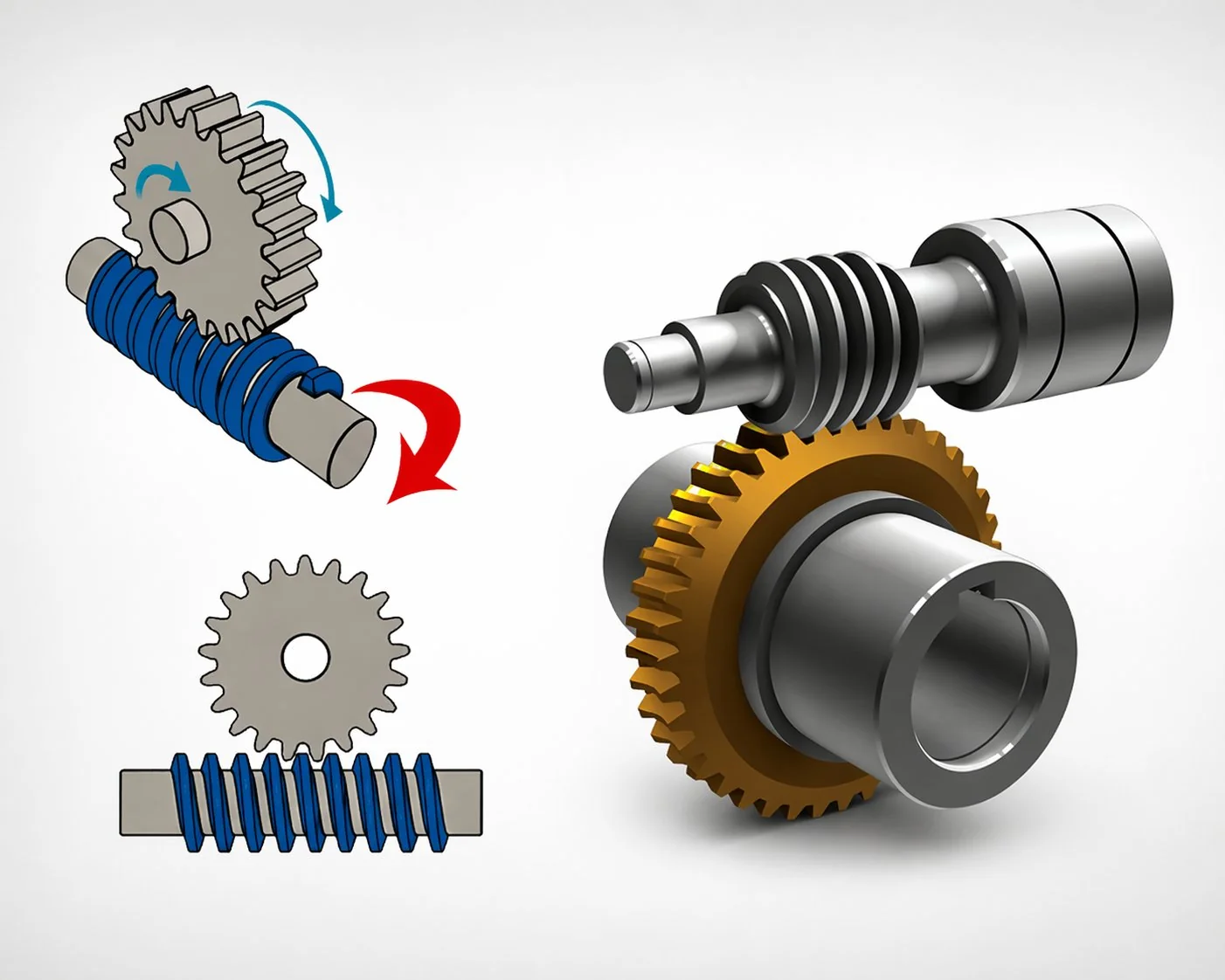
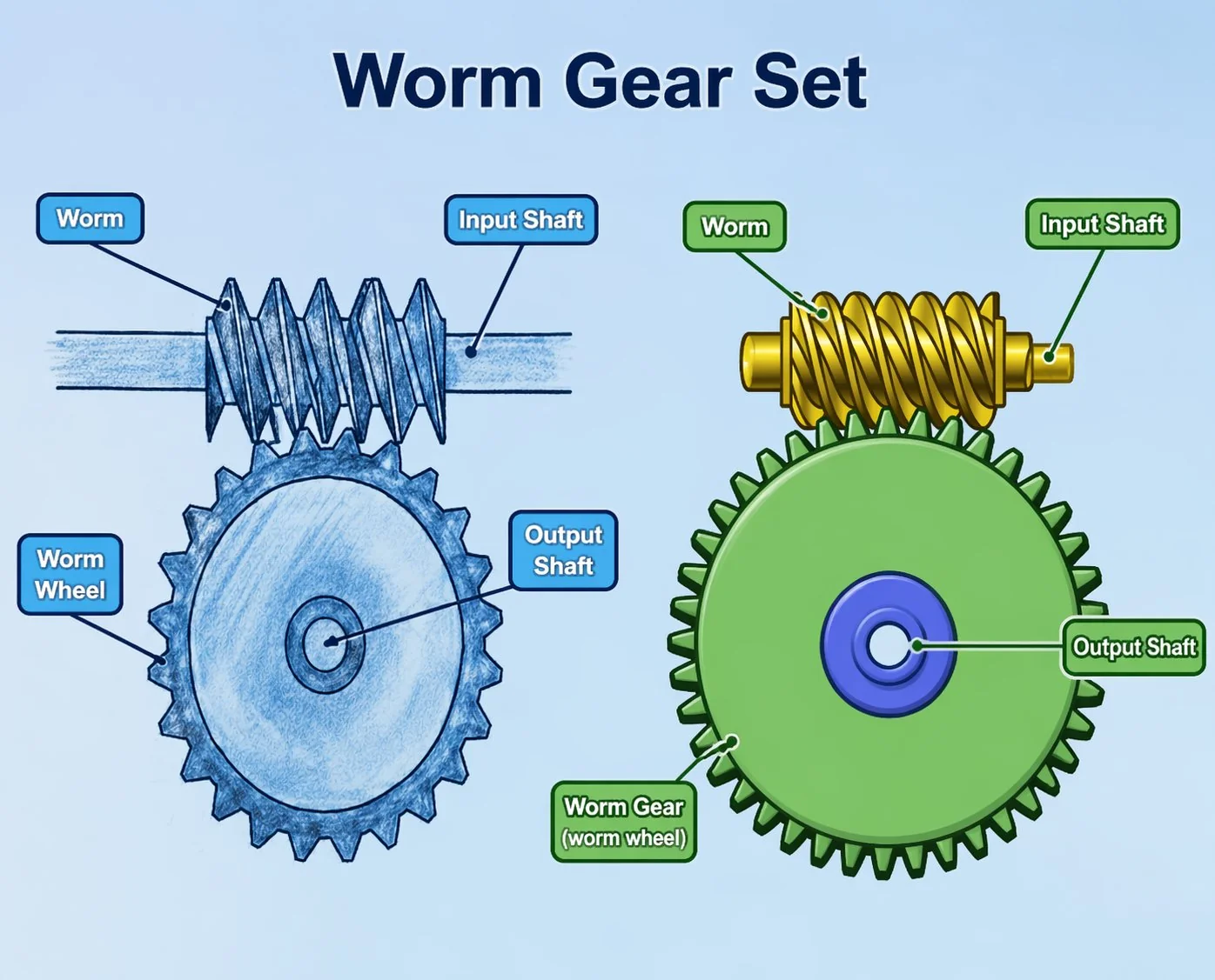
Worm and Worm Wheel for Grinding and Polishing Machine Drives
An optical lens polisher produces a surface flatness of 0.05 µm — roughly one-thousandth the thickness of a human hair. At this scale, every source of vibration in the machine leaves its signature on the finished surface. The worm gear pair driving the polishing spindle must contribute less than 0.002 mm/s of mesh vibration — an order of magnitude quieter than a premium elevator drive and two orders below a standard industrial reducer.
Grinding and polishing machines produce the finest surface finishes in manufacturing — Ra 0.05 to 0.8 µm — and any vibration from the drive system imprints directly on the finished surface as periodic waviness or roughness degradation. The vibration-to-surface-quality analysis quantifies how worm gear mesh vibration amplitude at the mesh frequency translates to surface roughness contribution: each 0.01 mm/s of mesh vibration adds approximately 0.02 to 0.05 µm to the surface Ra value. For a surface grinder targeting Ra 0.2 µm, the worm gear pair vibration budget is below 0.02 mm/s — achievable only with lapped or superfinished worms at Ra 0.1 to 0.2 µm and DIN accuracy class 3 to 4. For optical polishing at Ra 0.05 µm, the budget drops to below 0.005 mm/s — requiring class 2 worm gear pairs that are individually lapped and vibration-tested. Speed stability within plus or minus 0.5 percent is mandatory because grinding wheel material removal rate is proportional to table speed — a 1 percent speed variation produces 1 percent depth-of-cut variation that exceeds the total form tolerance on precision ground components.
Why grinding and polishing machines need ultra-low-vibration drives
Grinding and polishing differ from milling and turning in a fundamental way: the depth of cut is measured in single-digit micrometres (1 to 20 µm per pass) rather than millimetres. At this scale, the distinction between intentional material removal and vibration-induced surface damage blurs — a 5 µm vibration displacement at the contact point removes 5 µm of material on the vibration peak and zero on the trough, producing a surface waviness equal to the vibration amplitude. The machined surface becomes a recording of every vibration source in the machine.
The worm gear pair is one of 5 to 8 vibration sources in a typical grinder (others include the grinding wheel spindle bearings, the wheel imbalance, the hydraulic pump, the coolant pump, and the machine base). Each source must stay within its allocated vibration budget so that the combined total stays below the surface quality threshold. The worm gear pair’s contribution comes from two mechanisms: mesh-frequency excitation (the periodic tooth engagement as the worm rotates) and transmission error (micro-variations in output speed per input revolution due to tooth geometry imperfections).
The sliding engagement of each worm thread with the wheel tooth produces a periodic force at the mesh frequency (worm RPM for single-start). This force excites the machine structure. Smoother tooth surfaces (lower Ra) reduce the excitation amplitude — the primary reason lapped worms are specified for grinders.
Imperfections in tooth geometry cause the output to speed up and slow down slightly within each revolution — a micro-variation called transmission error. This variation translates directly to table-speed variation, which produces workpiece surface waviness at the worm rotation period. DIN class 3 to 4 minimises transmission error.
If the mesh frequency coincides with a machine structural resonance (10 to 200 Hz range), even small excitation amplitudes produce large vibration at the grinding contact point. Changing the worm input speed by 5 to 10 percent can shift the mesh frequency away from the resonance — a tuning adjustment that requires no hardware change.
Vibration-to-surface-quality analysis — from mm/s at the mesh to µm Ra on the workpiece
The relationship between worm gear pair mesh vibration and ground surface roughness depends on the vibration amplitude, the structural transfer path from the gear housing to the grinding contact, and the grinding process parameters (wheel speed, depth of cut, coolant). The transfer function varies by machine design, but empirical data across a range of surface and cylindrical grinders shows a consistent rule of thumb: each 0.01 mm/s RMS of mesh vibration at the worm gear housing contributes approximately 0.02 to 0.05 µm to the workpiece surface Ra value.
The table reveals the precision hierarchy: a hobbed worm at Ra 1.6 µm contributes 0.16 to 0.75 µm of surface roughness from vibration alone — rendering it useless for any grinding application (it would exceed the entire surface roughness budget before the grinding wheel even contacts the workpiece). Ground worms at Ra 0.4 µm are adequate for industrial centreless and rough surface grinding. Lapped worms at Ra 0.2 µm serve precision surface and cylindrical grinding. Superfinished worms at Ra 0.1 µm are reserved for optical polishing and semiconductor processes where the target surface roughness is below 0.1 µm.
A Korean precision surface grinder manufacturer received complaints from a bearing manufacturer customer: ground bearing races showed periodic waviness at a frequency that did not correspond to the grinding wheel RPM, the workhead RPM, or the hydraulic pump frequency. The waviness wavelength was 0.42 mm — matching the table advance per worm revolution at the specified feed rate (worm gear pair ratio 30:1, lead screw pitch 5 mm, one worm revolution = 0.167 mm table travel × 2.5 grinding passes per worm revolution at the specific speed combination = 0.42 mm surface pattern). The worm gear pair had been replaced during a recent overhaul with a ground worm at Ra 0.35 µm — meeting the purchase specification of “Ra below 0.4 µm.” However, vibration measurement showed 0.04 mm/s at the mesh frequency — at the upper boundary of the acceptable range for Ra 0.2 µm target surface finish on the bearing races. The original factory-installed worm had been lapped to Ra 0.18 µm with vibration of 0.012 mm/s. Resolution: the replacement worm was lapped to Ra 0.15 µm (additional cost 35 USD), vibration reduced to 0.008 mm/s, and the periodic waviness disappeared. Lesson: grinding machine worm specifications should state the vibration limit at the mesh frequency (mm/s RMS) in addition to the surface finish Ra — because two worms at the same Ra can produce different vibration levels due to differences in tooth profile accuracy that Ra does not capture.
Speed stability — consistent material removal across the grinding pass
Beyond vibration, the gear pair must deliver consistent output speed — because the material removal rate in grinding is directly proportional to the table feed speed. If the feed varies by 2 percent during a cross-feed pass, the depth of cut varies by 2 percent, producing a form error that may exceed the total tolerance on precision-ground components. Speed stability within plus or minus 0.5 percent requires DIN class 4 or better tooth geometry with transmission error below 5 arcseconds peak-to-peak — the same accuracy grade as CNC rotary table specification (Article A22) but for a different functional reason: position accuracy versus feed consistency.
Three grinding and polishing machine worm gear pair cases
Case 1 — Korean precision surface grinder: Ra 0.2 µm target, bearing race application
A Korean surface grinder manufacturer specified worm gear pairs for the longitudinal table feed drive of a precision surface grinder used for bearing race finishing. Target surface roughness: Ra 0.2 µm. Table size: 600 × 300 mm. Feed rate: 1 to 15 m/min (hydraulic reciprocating with worm-gear-driven cross-feed index). Worm gear pair for cross-feed index: single-start, module 1.5, centre distance 30 mm, ratio 30:1, lapped Ra 0.15 µm, DIN accuracy class 4. Vibration at mesh frequency: 0.008 mm/s RMS (verified by accelerometer during factory acceptance test). Ra contribution from gear vibration: approximately 0.02 µm — consuming 10 percent of the 0.2 µm budget. Material: carburised 18CrNiMo7-6 worm, HRC 60, centrifugal-cast phosphor bronze wheel. Lubrication: ISO VG 32 spindle oil (shared with table slideways). Cost per pair: 185 USD. The grinder produced bearing races at Ra 0.15 µm consistently — comfortably within the 0.2 µm target.
Case 2 — Japanese optical lens polisher: Ra 0.05 µm, superfinished worm, vibration-tested
A Japanese optical equipment manufacturer specified a worm gear pair for the spindle drive of an automated lens polishing machine producing camera and microscope optics. Target surface flatness: 0.05 µm (one-quarter wavelength of visible light). The worm gear pair drove the polishing spindle at 15 to 60 RPM through a 40:1 ratio. Vibration budget for the drive: below 0.003 mm/s RMS at the mesh frequency. Worm gear pair: single-start, module 1, centre distance 25 mm, ratio 40:1, superfinished Ra 0.08 µm, DIN accuracy class 2. Each pair was individually vibration-tested on a dedicated test rig at the target speed range — pairs exceeding 0.003 mm/s were rejected (approximately 15 percent rejection rate, reflecting the extreme tolerance). Material: nitrided 31CrMoV9 worm, HRC 62 surface, centrifugal-cast tin bronze with antimony addition (superior running-in characteristics for minimal initial wear-in vibration). Cost per pair: 680 USD (including individual vibration test certificate). Browse low vibration worm gear drive options for precision grinding and optical polishing applications.
Case 3 — Vietnamese centreless grinder: Ra 0.8 µm, ground worm, production volume
A Vietnamese machine tool manufacturer specified worm gear pairs for the regulating wheel drive of a centreless grinder producing steel pins and shafts. Target surface roughness: Ra 0.8 µm (industrial grade). Regulating wheel speed: 10 to 40 RPM. Motor: 0.75 kW VFD-controlled. Ratio: 25:1. Output torque: 45 N·m. The relaxed Ra 0.8 µm target allowed a ground worm at Ra 0.4 µm — the vibration contribution of approximately 0.1 µm consumed only 12 percent of the 0.8 µm budget. Lapped finish was unnecessary and would have added 40 percent to the pair cost without measurable quality benefit at this tolerance level. Worm gear pair: single-start, module 2, centre distance 40 mm, DIN accuracy class 6. Material: case-hardened carbon steel worm, phosphor bronze wheel. Coolant protection: EPDM seal IP55 with splash guard (centreless grinding coolant is directed at the grinding zone, not the drive). Cost per pair: 52 USD. Annual production: 200 centreless grinders (200 pairs per year). The specification demonstrates that grinding machine worm gear pair quality must match the process target — superfinishing a worm for an Ra 0.8 µm centreless grinder wastes 70 percent of the additional finishing cost.
คำถามที่พบบ่อย
Q: How do I measure the worm gear pair vibration contribution on an existing grinder?
Mount an accelerometer on the worm gear housing and measure the vibration spectrum during table feed operation (grinding wheel not cutting — isolating the drive vibration from the process vibration). Identify the peak at the worm mesh frequency (single-start: peak at worm RPM in Hz). Compare this peak amplitude (in mm/s RMS) to the vibration-to-surface-quality table to estimate the Ra contribution. If the peak exceeds the budget for your target surface finish, either replace the worm with a finer finish or adjust the worm input speed by 5 to 10 percent to shift the mesh frequency away from any structural resonance.
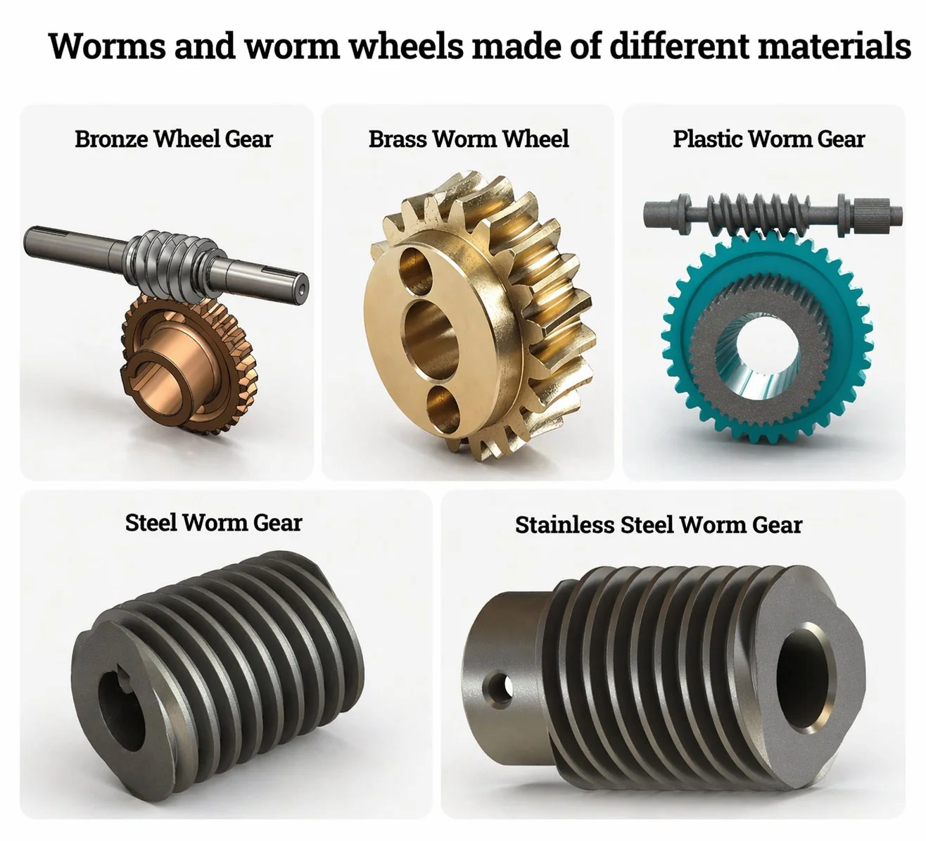
Q: Does the worm gear pair material affect vibration?
Yes — the wheel material has a significant effect. Bronze wheels dampen mesh vibration through internal material damping (bronze has higher damping capacity than steel). POM and MC Nylon wheels provide even higher damping — 3 to 5 times more than bronze — but are limited to very light loads (below 20 N·m). For precision grinders at moderate torque (20 to 80 N·m), bronze is the standard. For ultra-precision optical polishing at very light torque (below 10 N·m), POM wheels can provide an additional 2 to 4 dB(A) noise reduction and measurably lower vibration — but at the cost of shorter wheel life and lower position accuracy due to plastic dimensional instability.
Q: Can grinding coolant damage the worm gear pair?
Grinding coolant (typically water-soluble cutting fluid at 3 to 8 percent concentration) is moderately corrosive and contains abrasive swarf (ground metal particles). If coolant enters the worm gear housing through degraded seals, two problems develop: the water content emulsifies the spindle oil (reducing lubrication), and the swarf particles act as lapping compound on the gear tooth surfaces (accelerating wear and increasing backlash). The result is measurable within months — vibration increases and surface quality degrades. EPDM seals (resistant to water-soluble coolant) and positive air purge at the shaft entry are the standard protection. Oil analysis every 6 months (water content below 0.05 percent, particle count below ISO 18/16/13) monitors seal effectiveness.
Q: Why specify vibration (mm/s) in addition to surface finish (Ra) for the worm?
Surface finish Ra measures the average roughness of the worm thread surface — it indicates how smooth the surface is at a micro-geometric level. Vibration (mm/s at mesh frequency) measures the dynamic excitation that the worm gear pair produces during rotation — it indicates how much the pair shakes the machine. Two worms with identical Ra values can produce different vibration levels because vibration also depends on tooth profile accuracy, lead accuracy, and concentricity — parameters that Ra does not capture. For grinding applications, the vibration specification is more directly relevant to the finished surface quality than the worm Ra alone. Specify both: Ra for manufacturing control, vibration for functional verification.
Q: What is the typical service life of a grinding machine worm gear pair?
Grinding machines run 2,000 to 4,000 hours per year with intermittent feed duty (the worm gear pair operates during cross-feed index strokes, not continuously). At this duty and the light torques typical of grinding (10 to 80 N·m), the bronze wheel lasts 8 to 15 years. The life-limiting factor is vibration degradation rather than backlash — as the wheel wears, the contact pattern changes and the mesh excitation increases. When vibration at the mesh frequency rises to double the original value, the surface quality begins to degrade. Plan wheel replacement when vibration doubles — typically at 60 to 70 percent of the backlash-limited mechanical life.
Grinding and polishing machines operate at the finest end of the manufacturing precision spectrum — and the worm gear pair driving the table feed or spindle is one of the few components whose vibration signature can be directly measured on the finished workpiece surface. The vibration-to-surface-quality analysis (each 0.01 mm/s mesh vibration adds 0.02 to 0.05 µm to the surface Ra) quantifies why hobbed worms are unusable for grinding, ground worms serve industrial grinding, lapped worms serve precision grinding, and superfinished worms serve optical polishing. The vibration limit at the mesh frequency (mm/s RMS) should be specified alongside the worm surface finish (Ra µm) — because Ra alone does not predict vibration performance. For grinding machine builders, the worm gear pair specification determines the finest surface finish the machine can achieve — it is a capability-defining component, not just a drive element.
For grinding and polishing machine manufacturers, our engineering desk provides worm gear pairs with individual vibration test certificates for precision applications. Standard catalogue precision worm gear sets include ground, lapped, and superfinished configurations with DIN class 2 to 6 accuracy. Submit a grinding drive specification with target surface roughness, table speed range, and vibration budget.
Specifying worm gear pairs for grinding or polishing machines?
Send target surface roughness (Ra), table or spindle speed, vibration budget (if known), and grinding type (surface, cylindrical, centreless, optical). We will recommend the worm finish grade, DIN class, and provide individual vibration test certificates for precision applications.
บรรณาธิการ: Cxm


