Primjena pužnih prijenosnika — Transporteri, Dizalice, Mikseri, Aktuatori
Four deep dives into the applications that buy 80 percent of all worm gear sets. Specifications, common variants, and the design choices that distinguish a successful project from a recurring breakdown.
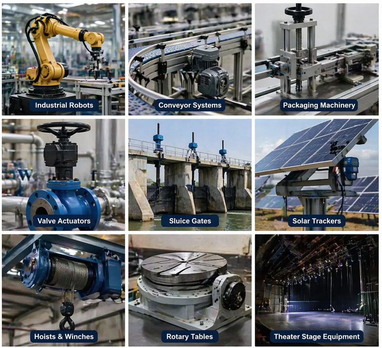
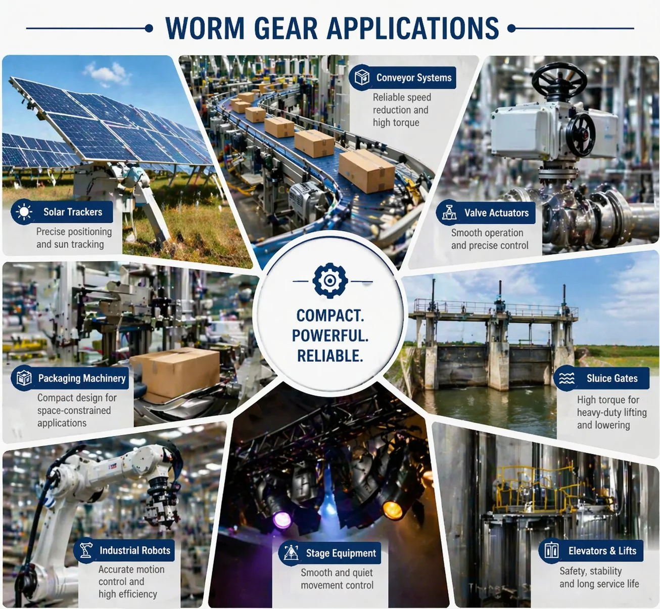
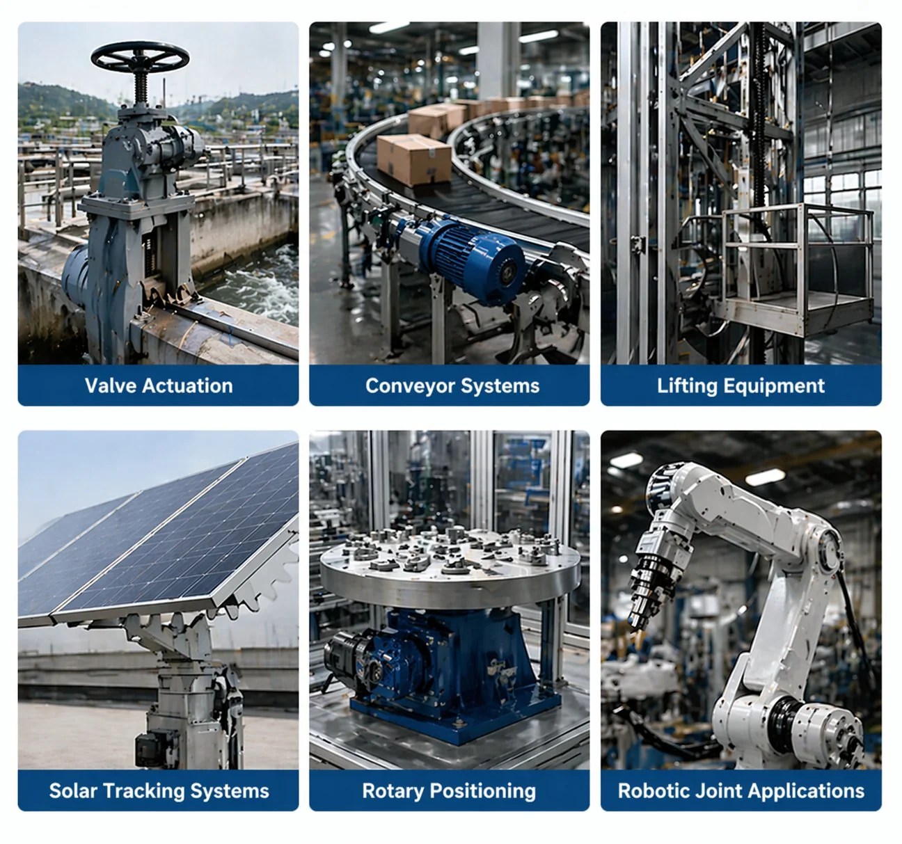
Four application categories account for roughly 80 percent of industrial worm and worm wheel sales: belt and screw conveyors (10:1 to 30:1, intermittent to continuous duty), hoists and lifting equipment (40:1 to 80:1, self-locking mandatory), mixers and agitators (15:1 to 50:1, variable load), and linear actuators (60:1 to 200:1, position-holding). Each category has distinct design priorities — conveyors prize cost and quiet operation, hoists prize self-locking and shock tolerance, mixers prize torque density and seal quality, actuators prize backlash control and load-holding. Matching the spec to the application matters more than picking the largest standard frame size that meets the torque rating.
Why most application articles miss the point
Open any worm gear application page and you will see the same twelve-to-fifteen-item list — conveyors, hoists, packaging, mixers, valve actuators, gates — each described in one sentence: “worm gears are used in X for high torque and self-locking.” Useless to anyone specifying a drive for a real project. A new engineer reading that list learns worm gears can be used in conveyors, but nothing about which ratio, what efficiency, what failure mode, or what frame size.
This article goes the other way. We pick the four largest application categories — conveyors, hoists, mixers, and actuators — and treat each one as a deep dive. For each category you get the typical torque and rpm ranges, the standard ratio band, the specific design issues that come up, the common variants, and a real OEM scenario showing how the specification gets written. Other applications appear in a final section, but the depth on the four primary categories should let you specify a drive for any of them with confidence.
Application 1 — Conveyors and material handling
Belt and screw conveyors are the largest single application for worm gear reducers globally. The combination of motor speed (typically 1,400 to 1,750 rpm) and conveyor pulley speed (10 to 50 rpm) needs reduction ratios in the 30:1 to 100:1 range, which lands squarely in worm gear’s sweet spot. Right-angle output fits the typical conveyor frame layout where the motor sits beside or under the conveyor, not in line with it.
Most general industrial conveyors run intermittent to moderate continuous duty, which sits well within the worm gear thermal envelope. Heavy 24-hour mining or quarry conveyors are the exception — those push past worm gear’s thermal limit and benefit from bevel-helical alternatives.
Typical specifications: output torque 20 to 800 N·m, output speed 10 to 60 rpm, ratio 30:1 to 60:1, 4-pole 3-phase induction motor at 1,400 rpm, single-throat worm wheel in phosphor bronze, ISO VG 460 compounded mineral oil, foot-mount cast-iron housing, keyway output shaft.
Design priorities: capital cost is usually the dominant procurement factor — conveyors are sold on price-per-metre, and the gear reducer is a significant fraction of the bill of materials. Quiet operation matters in indoor packaging plants. Service factor 1.3 to 1.7 is standard depending on whether the conveyor handles smooth product flow or shock-loaded material entry. Overhung load capacity at the output shaft drives frame size selection — the chain sprocket or pulley creates a side load that must be supported by the gearbox output bearings.
Common variants: for inclined conveyors, self-locking is sometimes specified to prevent reverse drift when the motor stops — choose ratio 50:1 or higher with a single-start worm. For washdown environments (food, beverage, pharmaceutical), specify stainless-steel housing or food-grade epoxy-coated cast iron with H1 lubricant. For dusty environments (cement, aggregate, agricultural), upgrade the seal package to lip-plus-dust-lip or labyrinth seals.
Real OEM scenario: Korean food packaging line, 25 metres long, transports 40 kg/m of product at 0.4 m/s, drive pulley 250 mm diameter, 16-hour daily operation. Calculation: pulley speed 30.6 rpm, belt force 100 N (rolling resistance dominant), pulley torque 12.5 N·m × 1.5 service factor = 18.8 N·m. Motor 1,400 rpm requires ratio 1400/30.6 = 45.8 → round to 50:1 (Z₁=1, Z₂=50). Final spec: 50:1 worm gear reducer, 0.37 kW motor, ISO VG 460 mineral oil, foot-mount cast iron housing with stainless overlay, yellow-metal-safe oil. Total cost roughly 35 percent below an equivalent helical alternative — and the annual electricity bill difference (about 250 USD) takes 3 years to overcome the capital saving.
Application 2 — Hoists and lifting equipment
Hoists are worm gear’s natural application — the self-locking property is the central reason worm gear technology exists, and it is what separates a hoist drive that holds the load safely from one that lets the load drift down when the motor stops. Self-locking is not optional for hoists; it is the defining feature.
However — self-locking is never the only safety device on a properly designed hoist. AGMA and equivalent bodies in Korea and Japan recommend a positive mechanical brake on any hoist load above a few tens of kilograms. Self-locking is auxiliary; the brake is primary. Vibration can momentarily reduce the effective friction angle and let a self-locked drive creep backward. Treat self-locking as the second line of defence.
Typical specifications: output torque 100 to 5,000 N·m (depending on lift capacity and drum radius), output speed 5 to 25 rpm, ratio 50:1 to 100:1 (single-start worm for self-locking), 4-pole motor at 1,400 rpm, single or double-throat worm wheel in phosphor bronze for moderate duty, aluminium bronze for heavy continuous service, ISO VG 460 to 680 mineral or PAO synthetic, foot or flange-mount cast iron housing.
Design priorities: service factor 2.0 to 2.5 because hoist applications include shock loads from load engagement and end-stop impacts. The lead angle must stay below 5 to 6 degrees for reliable self-locking — multi-start worm geometries are excluded. Efficiency is a secondary concern; a hoist running 200 hours per year does not justify chasing 5 percentage points of efficiency. Brake interface is often integral — the motor is supplied with a fail-safe brake on the input shaft, so brake-release coordination with the gearbox is part of the system design.
Common variants: manual chain-pull hoists use very high ratios (100:1 to 200:1) so that human-scale input torque (tens of N·m on a chain wheel) can lift the rated load. Powered hoists with frequency-controlled motors run at lower ratios because variable speed handles the slow-lift requirement. Crane hoists often use double-throat worm geometry for the higher torque density required at large lift capacities. Vehicle lifts (automotive service jacks, scissor lifts) use compact actuator-style worm drives with integrated leadscrew output.
Real OEM scenario: Vietnamese construction equipment manufacturer, 1,000 kg material hoist, 150 mm radius drum, lift speed 8 m/min, intermittent duty (5 minutes on, 30 minutes off). Calculation: drum torque 1000 × 9.81 × 0.15 = 1,471 N·m × 2.0 service factor = 2,942 N·m. Drum rpm 8 / (60 × 2π × 0.15) × 60 = 8.5 rpm. Motor 1,400 rpm requires ratio 1400/8.5 = 165 → round to 160:1 too high for single-stage worm. Solution: 80:1 worm primary stage plus a 2:1 spur secondary stage gives 160:1 total. Self-locking maintained on the worm stage. Final spec: 80:1 worm reducer (Z₁=1, Z₂=80), 5.5 kW motor with fail-safe brake, ISO VG 680 PAO synthetic for thermal margin, double-throat aluminium bronze worm wheel for shock tolerance, foot-mount housing.
Application 3 — Mixers and agitators
Mixers and agitators in food, pharmaceutical, chemical, and water-treatment industries make heavy use of worm gear drives because the application combines low output speed, moderate to high torque, vertical mounting orientation, and frequent regulatory requirements that worm gear technology handles well.
The vertical mounting orientation matters more than first-time specifiers expect. Standard horizontal-mount catalogue gearboxes have a specific oil fill level for splash lubrication; inverting them onto a vertical agitator shaft changes the worm immersion depth and often requires a different oil fill specification.
Typical specifications: output torque 50 to 1,200 N·m, output speed 30 to 120 rpm, ratio 15:1 to 50:1, 4-pole motor at 1,400 rpm, single-throat worm wheel in phosphor bronze for water and food processing, 17-4PH stainless worm with 316 stainless wheel for pharma and corrosive chemistry, ISO VG 460 NSF H1 mineral or PAG polyglycol depending on regulatory class, vertical-mount cast iron or stainless housing.
Design priorities: seal quality drives the procurement decision more than for any other application. Mixer shafts pass through the gearbox seal into the process vessel — a leaking seal contaminates the product and triggers a regulatory event. Most mixer drives specify double-lip output seals or labyrinth seals plus inert-gas purge for sterile applications. Service factor 1.5 to 2.0 to handle viscosity variations during mixing cycles. Vertical-mount oil retention is the second priority — confirm the supplier’s vertical-mount fill specification, not the horizontal default.
Common variants: sanitary processing (food, pharma, biotech) requires stainless steel components and NSF H1 lubricants — costlier per unit but mandatory for regulatory compliance. Heavy chemical mixers running continuous duty may use PAG polyglycol oil for thermal margin and extended drain interval. Pharmaceutical applications often specify EHEDG-certified housings with crevice-free welded construction. Water treatment and wastewater mixers typically use phosphor bronze in cast-iron housing for cost optimisation.
Real OEM scenario: Japanese pharmaceutical equipment OEM, 200-litre process tank with 4-blade impeller, mixing speed 60 rpm, batch viscosity 200 to 800 cP (peak during cold start), 16-hour daily operation, FDA/EHEDG compliance required. Calculation: peak torque from impeller drag at viscosity 800 cP estimated at 95 N·m × 1.7 service factor = 161 N·m. Motor 1,400 rpm requires ratio 1400/60 = 23.3 → round to 25:1 (Z₁=2, Z₂=50). Multi-start for higher efficiency since self-locking is not required. Final spec: 25:1 worm reducer, 17-4PH stainless worm with 316 stainless wheel, NSF H1 ISO VG 460 mineral oil, vertical-mount EHEDG-compliant stainless housing with crevice-free welds, double-lip output seal with inert gas purge connection. Cost roughly 3.2× the equivalent food-grade phosphor bronze unit, but regulatory compliance is non-negotiable.
Application 4 — Linear actuators
Linear actuators convert rotary motor input into linear shaft motion through a leadscrew, ballscrew, or trapezoidal screw. Worm gear primary stages drive the screw at the right speed for typical actuator stroke rates, with the self-locking property holding position when the motor is off.
Applications include solar trackers, hospital beds, telescoping antennas, automated gates, valve operators, and electric jacks — anywhere linear motion needs to be slow, controlled, and self-holding.
Linear actuators differ from rotary applications in one important way: the output is not torque, it is force at the screw. The worm gear sizing calculation has to convert linear force at the rated stroke speed back to rotary torque at the screw input, then apply the worm gear reduction. This conversion catches first-time specifiers who size the worm gear directly against the linear force without going through the screw mechanics.
Typical specifications: output torque at screw 20 to 500 N·m, screw rotation 30 to 200 rpm depending on lead, ratio 60:1 to 200:1, 12V or 24V DC motor at 3,000 to 5,000 rpm (small actuators) or 4-pole AC motor at 1,400 rpm (industrial actuators), single-start worm wheel in bronze or plastic for small actuators, integral leadscrew output, compact integrated housing.
Design priorities: position-holding capability — the actuator must hold the load when power is removed. Self-locking is therefore mandatory for vertical-load applications. Backlash control matters when the actuator participates in a closed-loop control system; mechanical backlash translates directly into positioning hysteresis. Compact size drives the integrated-housing geometry that distinguishes actuators from general-purpose worm gear reducers. Duty cycle is usually intermittent (a few minutes on per hour of operation), which keeps thermal management simple.
Common variants: medical bed and patient lift actuators use plastic worm gears (POM acetal worm, PA66 nylon wheel) for cost and silent operation under light loads. Solar tracker actuators use bronze worm wheel with steel worm for outdoor durability and 25-year service life. Heavy industrial actuators (gate operators, large valve actuators) use bronze wheel with cast-iron housing scaled up to handle hundreds of N·m output torque. Encoder feedback options are common for closed-loop position control.
Real OEM scenario: Korean solar tracker manufacturer, single-axis tracker for utility-scale plant, 4-metre azimuth length carrying 120 kg of PV modules, peak wind load 800 N at module surface, 0.5 degrees per minute slewing rate, outdoor service 25-year design life. Calculation: peak torque at slew shaft 800 × 2.0 m moment arm = 1,600 N·m × 1.5 service factor = 2,400 N·m. Slew rate 0.5 deg/min = 0.0083 rpm — extremely slow. Motor 1,400 rpm requires ratio 1400/0.0083 ≈ 169,000 — far too high for any single drive. Solution: 100:1 worm primary stage plus 60:1 leadscrew secondary, total 6,000:1 reduction, with the slew rate handled by short bursts of motor activation rather than continuous slow rotation. Final spec: 100:1 single-start worm reducer with self-locking, aluminium bronze worm wheel for environmental durability, integrated leadscrew output, sealed-for-life housing rated IP66 for outdoor exposure. Browse complete pužni reduktor options if a similar high-ratio outdoor application matches your requirements.
When customers send specifications for “a worm gear for my application,” about 40 percent of the time the specification arrives with a torque number that was estimated from the linear force or pulley load without the conversion through screw lead or pulley radius. The number is sometimes off by a factor of 2 to 5. Before settling on a frame size, always work backward from the load: linear force times screw lead divided by 2π gives the screw torque; pulley tangential force times pulley radius gives the pulley torque. The worm gear sees that converted torque, not the original load force. This single calculation step prevents most first-time sizing errors.
Other applications worth knowing
Beyond the four primary categories above, worm gear technology serves a long tail of secondary applications, each with its own specification quirks. Brief summaries below for the most common.
The application breadth is wide because the worm gear’s combination of high single-stage ratio, right-angle layout, optional self-locking, and low cost solves problems that other gear types cannot solve simultaneously. What stays consistent across applications is the engineering discipline — define the requirement, calculate the load correctly, choose the right ratio and material, specify the right lubricant. Skip any of those steps and the application appears in the failure mode statistics rather than the success stories.
Često postavljana pitanja
Q: Does the same worm gear specification work for vertical and horizontal mixers?
The mechanical specification (torque, ratio, frame size) is identical, but the lubrication setup differs. A horizontal-mount catalogue gearbox typically submerges the worm to roughly 30 percent of its diameter in the oil bath. Inverting the same gearbox to vertical mounting may leave the worm only 5 percent submerged at startup, which is inadequate for splash lubrication and causes scuffing within the first run-in period. Always confirm the supplier’s vertical-mount fill specification — most reputable suppliers have a vertical-mount variant or modify the standard fill volume on request. Specifying “vertical input” or “vertical output” explicitly in the order prevents confusion at delivery.
Q: When does a conveyor application benefit from a complete reducer rather than a bare worm and worm wheel set?
Almost always for industrial conveyors. A complete reducer arrives with the housing, bearings, seals, and lubricant pre-engineered and tested, and the integration cost on the customer side is minimal — bolt the unit to a frame, couple input and output, fill or check oil, run. A bare set requires the customer to design and machine a housing, source bearings and seals, fill with appropriate oil, and validate the assembly — economically rational only at very high production volumes (over 5,000 units annually) or in highly customised applications where no catalogue housing fits. For most conveyor projects the complete reducer wins on cost and lead time.
Q: How is service factor different across the four application categories?
Conveyors typically use 1.3 to 1.7 service factor depending on whether the load enters smoothly or with shock. Hoists use 2.0 to 2.5 because of engagement shock and end-stop impacts, plus the safety factor implied by lifting heavy loads. Mixers use 1.5 to 2.0 to handle viscosity variations during cold start and process changes. Linear actuators use 1.5 to 2.0 with extra emphasis on stall torque if the actuator can drive against a hard stop. The right service factor multiplies the calculated steady torque before frame size selection — undersizing here is the most expensive mistake in the specification process.
Q: For a small DC-motor application, can I use a plastic worm and worm wheel pair?
Yes, for output torque under 5 to 8 N·m and intermittent duty under 60°C. POM acetal worm with PA66 nylon wheel is the standard combination for automotive seat actuators, household appliance timers, and small office equipment. Plastic-on-plastic worm gear pairs are silent, self-lubricating (no oil bath needed), and very cheap in mass production. They are not suitable for continuous duty, ambient temperatures above 60°C, or torques above the threshold — a metal pair is required at that point. Mass-production tolerances on plastic gears are tighter than on bronze gears thanks to injection moulding precision, so backlash is sometimes lower on the plastic option than on a small bronze equivalent.
Q: What documentation should I expect with an OEM order for these applications?
Standard documentation includes dimensional drawing, ratio confirmation, oil specification, and a basic warranty. For OEM volume orders, request material certificates for both worm and worm wheel, hardness reports, geometric inspection record, and oil-fill record. For regulated applications (food, pharma, marine, medical), expect additional certification: NSF H1 lubricant compliance, EHEDG/3-A construction documentation, FDA material compliance, or DNV/ABS marine certification. Specify required documentation in the request for quotation — adding it after the order is placed often delays delivery and may not be possible without re-running production tests.
Q: Are there applications where worm gear is the wrong choice?
Yes. High-precision servo positioning (use planetary). Continuous heavy-duty over 24 hours (use bevel-helical for thermal margin). Parallel-shaft layouts where right-angle is not needed (use helical). Very high efficiency requirements where electricity cost dominates lifecycle expense (use helical or bevel-helical). Very low ratios under 5:1 where the worm gear’s compactness advantage disappears (use helical, planetary, or even direct-drive). For most other applications worm gear is at least viable; for many it is the most cost-effective answer; for some — the four primary categories covered above — it is genuinely the natural choice.
Q: How does Korean and Japanese OEM specification practice differ from European or American?
Korean and Japanese OEM design practice emphasises documentation thoroughness — material certificates, hardness records, and JIS standard references are typically expected as standard delivery, not as upgrades. Module sizing follows JIS B1701 (metric) almost exclusively in both countries, with imperial sizes appearing only on equipment exported to North American customers. Lead times are slightly tighter than European norms, with 4 to 6 weeks for standard catalogue orders being common. Quality acceptance testing on incoming gearboxes is more rigorous in automotive Tier-1 supply chains than in general industrial — first-article inspection is the rule, not the exception. Specifications written for Korean or Japanese OEM use should reference JIS standards explicitly and include documentation requirements upfront.
The four categories above — conveyors, hoists, mixers, and linear actuators — define worm gear technology’s real industrial footprint. Each has its own specification norms, design priorities, and typical failure modes. Knowing which category your application falls into is the first step in writing a specification that gets a meaningful quote. The list of “applications worm gear is used in” is long; the list of “applications where worm gear is genuinely the right answer” is shorter, and these four sit firmly within it.
For Korean and Japanese OEM design teams specifying worm gear drives for any of these applications, our engineering desk reviews the load calculation, recommends the right ratio and material pair, and quotes against the matching Pužni zupčanici od fosforne bronze i nehrđajućeg čelika in our standard catalogue. Custom geometries for unusual application requirements are made to order against drawing — request an application-specific specification review with your duty cycle and load profile and our team will return a recommendation within one Korean working day.
Specifying for a conveyor, hoist, mixer, or actuator?
Send the application type, output torque, output rpm, duty cycle, and any regulatory requirements. We will recommend the ratio, material pair, lubricant, and frame size that matches — typically within one Korean working day for standard catalogue specifications.
Urednik: Cxm


