Korea Ever-Power · Application Engineering Guide
Worm and Worm Wheel for CNC Rotary Table Indexing
A 5-axis CNC machining centre cuts a turbine blade at 12,000 RPM spindle speed. The 4th-axis rotary table positions the blade blank to within 10 arcseconds — 0.003 degrees — and holds it against 800 N of cutting force while coolant floods the work zone at 20 litres per minute. The worm gear pair inside the rotary table is simultaneously a precision angular positioner, a workholding clamp, and a coolant-resistant mechanical component. It is the most precision-demanding worm gear application in any industry.
CNC rotary tables (4th and 5th axis) use worm gear pairs for precision angular positioning, continuous contouring during simultaneous multi-axis machining, and self-locking workholding against cutting forces. The backlash-to-position-error table quantifies how worm gear pair backlash translates to machining error at the workpiece cutting point: e = R × B / 3,438, where R is the workpiece radius in mm and B is the backlash in arcminutes. For a 200 mm radius workpiece, 1 arcminute of backlash produces 58 µm of position error — exceeding the typical CNC tolerance of plus or minus 25 µm. This is why CNC rotary table worm gear pairs universally use preloaded anti-backlash mechanisms (spring-loaded split wheel or shim-adjusted duplex) to reduce effective backlash to below 10 arcseconds. The ratio 360:1 is the CNC standard — one degree per worm revolution — enabling direct angular readout from the servo encoder without additional electronic gearing. DIN 3974 accuracy class 3 to 5 is specified for production-grade CNC rotary tables.
Why CNC rotary tables use worm gear drives
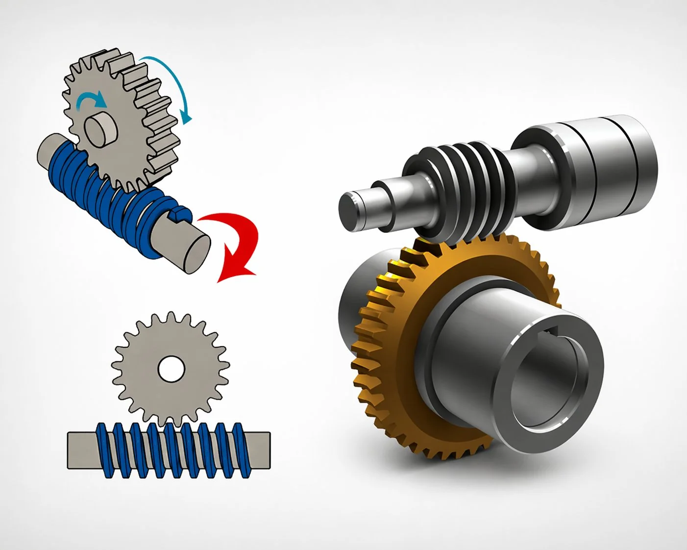
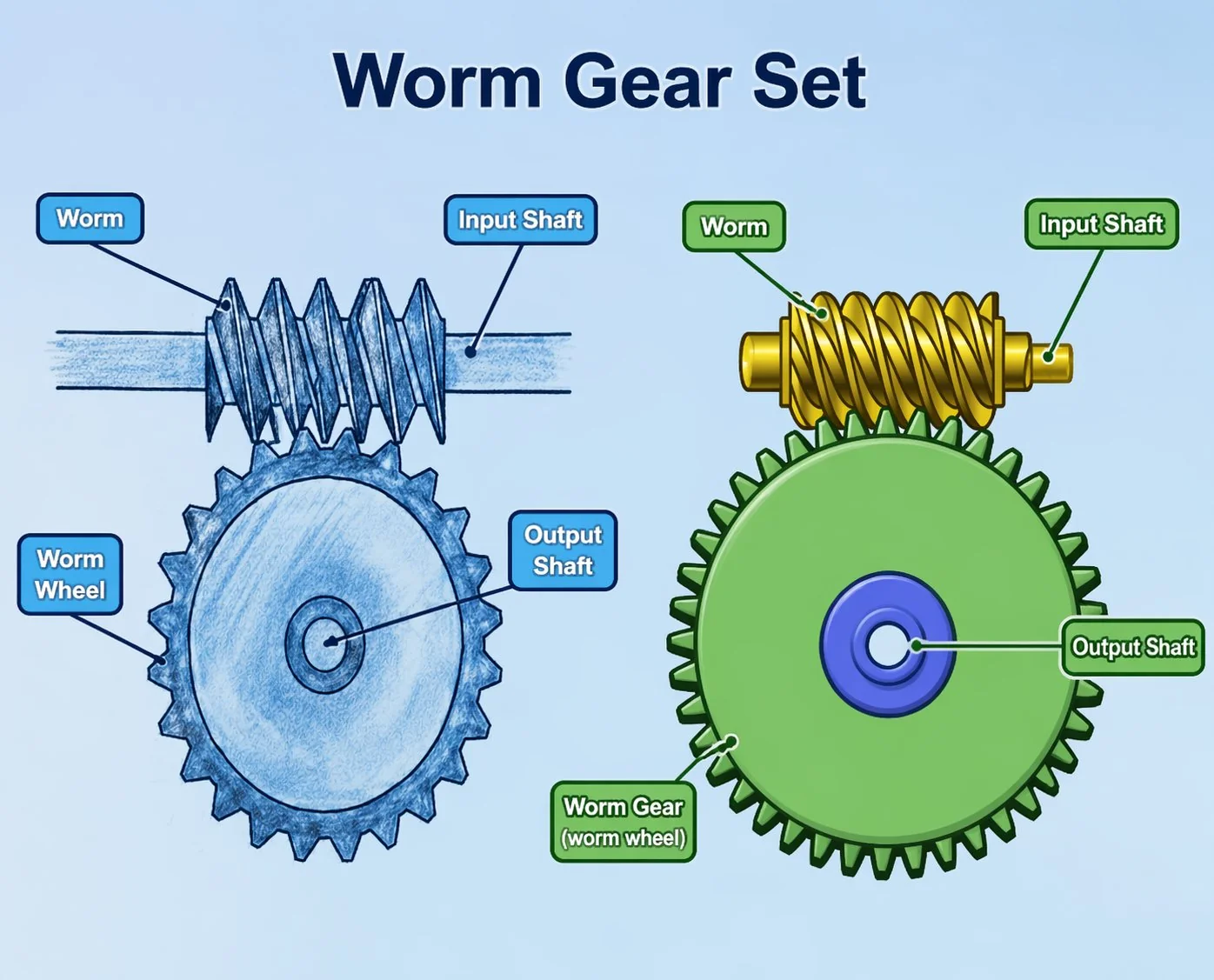
A CNC rotary table performs three functions simultaneously: it positions the workpiece at a precise angle, it holds the workpiece rigidly during cutting, and it rotates continuously during contouring operations (gear cutting, cam milling, blade machining). The worm gear pair provides all three functions in a single mechanical stage — no other gear type can match this combination.
The 360:1 ratio converts one full worm revolution to exactly one degree of table rotation. A servo motor with 10,000-count encoder provides 10,000 × 360 = 3,600,000 counts per table revolution — angular resolution of 0.36 arcseconds per count. Mechanical accuracy to plus or minus 10 arcseconds is achievable with DIN class 3 worm gear pairs.
During milling, the cutting force attempts to rotate the workpiece away from the indexed position. Self-locking resists this force without a separate hydraulic clamp — the cutting force at the workpiece radius produces a back-driving torque that the worm gear pair absorbs through its irreversibility.
In 4th-axis simultaneous machining, the table rotates continuously while the spindle moves in X/Y/Z — all axes synchronised by the CNC controller. The worm gear pair must deliver smooth, backlash-free rotation at variable speeds from 0.1 to 30 RPM without transmission error that would produce surface finish defects on the workpiece.
Backlash-to-position-error table — from arcminutes to microns at the cutting point
The relationship between worm gear pair backlash and machining error is purely geometric: the angular backlash at the table centre produces a linear position error at the workpiece radius that increases proportionally with the distance from the centre of rotation. The formula is e = R × B / 3,438 where e is the position error in mm, R is the workpiece radius (distance from table centre to cutting point) in mm, and B is the backlash in arcminutes.
The table makes the case for preloaded anti-backlash worm gear pairs in a single row: at R = 200 mm with standard 1-arcminute backlash, the position error is 58 µm — more than double the typical plus or minus 25 µm CNC machining tolerance. Even 0.5 arcminutes (30 arcseconds) produces 29 µm at 200 mm radius — still over the limit. Only the preloaded configuration at 10 arcseconds (0.15 arcminutes) stays comfortably within tolerance at 9 µm. General industrial worm gear pairs at 5 arcminutes are completely unusable for CNC indexing — the error at any practical workpiece radius exceeds the tolerance by an order of magnitude.
Anti-backlash preload methods — how CNC rotary tables achieve sub-10-arcsecond backlash
Standard worm gear pairs cannot achieve the sub-10-arcsecond backlash required for CNC indexing through manufacturing tolerance alone — the smallest achievable backlash in a conventional single-piece wheel is approximately 15 to 30 arcseconds at DIN class 3. To reach 5 to 10 arcseconds, the worm gear pair must be mechanically preloaded so that the tooth flanks maintain contact on both sides simultaneously, eliminating the free-play zone that constitutes backlash.
The wheel is split into two halves, each engaging the worm from opposite flanks. A spring between the halves pushes them apart, maintaining contact on both flanks simultaneously. Effective backlash: 3 to 8 arcseconds. Advantage: self-adjusting — the spring compensates for thermal expansion and minor wear. Disadvantage: limited torque capacity (the spring must be overcome before the teeth transmit full load). Best for: light-duty indexing tables (4th axis on vertical machining centres, dividing heads).
Two worm threads are machined on the same shaft with a slight axial offset. Shims between the worm bearing housings set the preload by controlling the axial position of the worm relative to the wheel. Effective backlash: 5 to 15 arcseconds. Advantage: full torque capacity (the preload is mechanical, not spring-limited). Disadvantage: requires re-shimming as the wheel wears (every 2 to 4 years). Best for: heavy-duty 5-axis tables, gear hobbing machines, and horizontal boring mill rotary tables.
A Korean CNC machine tool builder purchased replacement worm gear pairs for 15 tilting rotary tables (4th/5th axis combination) installed on horizontal machining centres. The original pairs were preloaded split-wheel type with 6 arcsecond effective backlash, DIN class 4. The replacement pairs from a different supplier were specified as “DIN class 4, anti-backlash” — but were shim-adjusted duplex type rather than spring-loaded split. Post-installation, the backlash measured 12 arcseconds — within the DIN class 4 tolerance but double the original 6 arcseconds. At the typical workpiece radius of 150 mm, the position error increased from 4 µm to 9 µm — still within the plus or minus 25 µm CNC tolerance for general machining but insufficient for a specific aerospace customer requiring plus or minus 10 µm on turbine blade root slots. The machine tool builder had to re-shim all 15 tables to achieve 8 arcseconds — 2 hours of skilled labour per table at 85 USD per hour, totalling 2,550 USD of unplanned labour. Lesson: “anti-backlash” is not a single specification — the preload method (split-wheel versus duplex worm), the effective backlash value (in arcseconds, not just “anti-backlash”), and the DIN accuracy class must all be specified explicitly. Two DIN class 4 anti-backlash pairs from different suppliers may deliver different backlash values because “class 4” defines tooth geometry tolerance, not preload effectiveness.
Three CNC rotary table worm gear pair specification cases
Case 1 — Korean 4th-axis rotary table: Ø250 mm, split-wheel, automotive parts
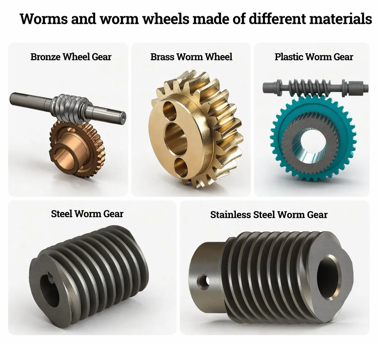
A Korean CNC machine tool manufacturer specified worm gear pairs for a 250 mm diameter 4th-axis rotary table designed for automotive component machining (aluminium and steel, workpiece radius up to 125 mm). Position accuracy required: plus or minus 15 arcseconds. Repeatability: plus or minus 5 arcseconds. Worm gear pair: single-start, module 1.5, wheel diameter 180 mm, ratio 360:1, DIN accuracy class 4. Preload: spring-loaded split wheel. Effective backlash: 6 arcseconds. Position error at R = 125 mm: 125 × 0.1 / 3,438 = 3.6 µm — well within the plus or minus 25 µm machining tolerance. Worm: hardened and ground 20CrMnTi steel, Ra 0.2 µm, HRC 58 to 62. Wheel: centrifugal-cast phosphor bronze CuSn12Ni. Lubrication: ISO VG 68 spindle oil (shared with table bearings), circulated by the machine’s central lube system. Motor: 1.5 kW AC servo with 131,072-count absolute encoder. Cost per worm gear pair assembly: 680 USD. Annual production: 400 tables (16,000 worm gear pair sets per year across the product family).
Case 2 — Japanese 5-axis tilting table: Ø400 mm, duplex worm, aerospace tolerance
A Japanese 5-axis machining centre manufacturer specified worm gear pairs for both the A-axis (tilt) and C-axis (rotation) of a 400 mm tilting rotary table designed for aerospace titanium and Inconel component machining. Position accuracy: plus or minus 8 arcseconds. The aerospace application required cutting forces up to 2,500 N at workpiece radius 180 mm — producing back-driving torque of 450 N·m at the table. The spring-loaded split-wheel design could not handle this torque (spring preload limited to approximately 150 N·m). Specification: shim-adjusted duplex worm. Module 2, wheel diameter 280 mm, ratio 360:1, DIN class 3. Effective backlash after shimming: 5 arcseconds. Position error at R = 180 mm: 180 × 0.083 / 3,438 = 4.4 µm — within the plus or minus 10 µm aerospace tolerance with 56 percent margin. Worm: carburised 18CrNiMo7-6, ground Ra 0.15 µm, HRC 60 to 63. Wheel: centrifugal-cast tin bronze with nickel addition (enhanced fatigue life for heavy-duty aerospace cutting). Coolant protection: labyrinth seal plus air purge at the worm shaft entry to prevent coolant ingress. Cost per worm gear pair assembly (A or C axis): 2,400 USD. Browse precision worm gear reducer options for CNC rotary table and machine tool applications.
Case 3 — Vietnamese manual dividing head: 40:1, non-preloaded, education and job shop
A Vietnamese machine tool distributor specified worm gear pairs for manual dividing heads sold to vocational training schools and small job shops. The dividing head mounts on a milling machine table and indexes the workpiece in fixed angular steps for cutting gear teeth, hexagonal flats, and equally spaced holes. Ratio: 40:1 (9 degrees per worm revolution — the standard dividing ratio that produces common divisions: 40 turns for full rotation, 20 turns for 180 degrees, 10 turns for 90 degrees). Non-preloaded (standard single-piece wheel with 2 to 3 arcminute backlash). Position error at R = 50 mm: 50 × 2.5 / 3,438 = 36 µm. This was acceptable for the typical plus or minus 0.1 mm (100 µm) tolerance of job-shop manual machining — the operator’s hand-wheel approach direction (always approaching from the same direction) effectively eliminates the backlash from the positioning. Worm: carbon steel, hobbed Ra 0.8 µm, hardened HRC 55. Wheel: sand-cast phosphor bronze. Cost per pair: 32 USD. The case demonstrates that not all machine tool indexing needs anti-backlash — manual operation with consistent approach direction eliminates the backlash effect that only appears in CNC bidirectional positioning.
Často kladené otázky
Q: Why is 360:1 the standard ratio for CNC rotary tables?
At 360:1, one full revolution of the worm rotates the table exactly one degree — making angular readout from the servo encoder straightforward: encoder counts per degree equal the encoder resolution per revolution. The CNC controller’s electronic gear ratio is 1:1, eliminating rounding errors in the position loop. Some specialised applications use 90:1 (for high-speed continuous contouring) or 720:1 (for ultra-fine angular resolution), but 360:1 is the standard for general-purpose indexing tables because it provides the best balance between angular resolution, output speed, and mechanical efficiency.
Q: How does machining heat affect worm gear pair accuracy?
Machining generates heat that flows from the workpiece and spindle into the table body, raising the table temperature by 5 to 20 degrees Celsius during extended cutting cycles. This thermal growth expands the wheel diameter and shifts the centre distance — increasing backlash by roughly 2 to 5 arcseconds per 10 degrees Celsius rise. For preloaded pairs, the thermal expansion may tighten the preload (reducing efficiency and increasing motor load) or loosen it (increasing backlash) depending on whether the wheel or the housing expands more. Spring-loaded split wheels are self-compensating for thermal growth; shim-adjusted duplex pairs are not — they require thermal stabilisation (warm-up cycle before precision machining) or active thermal compensation in the CNC controller. For aerospace machining with plus or minus 8 arcsecond requirements, a 30-minute warm-up cycle is standard practice before cutting the first workpiece.
Q: How is cutting coolant prevented from entering the worm gear housing?
CNC machining uses high-pressure coolant (10 to 70 bar) that floods the work zone and splashes onto the rotary table. Three sealing strategies protect the worm gear pair: labyrinth seal at the table body-to-housing interface (non-contact, no wear); positive air purge (0.1 to 0.3 bar compressed air continuously blowing outward through the labyrinth, preventing coolant ingress); and drain channels that route any coolant that passes the labyrinth away from the gear housing before it reaches the oil seal. Premium CNC tables use all three. If coolant enters the oil system, it emulsifies the spindle oil and produces accelerated wear on the worm and wheel contact surfaces — measurable as a backlash increase of 5 to 10 arcseconds within 6 months. Regular oil analysis (water content below 0.05 percent) monitors seal effectiveness.
Q: What is the typical service life of a CNC rotary table worm gear pair?
CNC rotary tables in production environments typically run 2,000 to 4,000 hours per year with intermittent indexing duty. The bronze wheel life is 5 to 10 years for general machining (steel and aluminium) and 3 to 6 years for heavy-duty aerospace machining (titanium, Inconel — higher cutting forces produce higher contact stress on the worm gear teeth). The steel worm lasts 10 to 20 years. The life-limiting factor is backlash growth beyond the acceptable machining tolerance — monitored by annual accuracy verification using a laser interferometer or precision polygon. Plan wheel replacement when the backlash exceeds twice the original preloaded value (e.g. replace when 6-arcsecond original grows to 12 arcseconds).
Q: Can a direct-drive torque motor replace the worm gear pair in CNC rotary tables?
Direct-drive torque motors (DDT) are used in high-speed 5-axis tables where continuous contouring speed above 50 RPM is needed. DDT eliminates the backlash issue entirely because there is no gear transmission. However, DDT lacks self-locking — a separate hydraulic clamp is needed to hold the table during cutting, adding cost and complexity. DDT also has lower torque density than a worm gear pair at low speed — a 400 mm DDT table costs 3 to 5 times more than an equivalent worm-gear table. For most production CNC machining (indexing plus moderate-speed contouring below 30 RPM), the worm gear pair remains more cost-effective than DDT. DDT is preferred only for high-speed continuous 5-axis machining of complex freeform surfaces where the contouring speed exceeds the worm gear pair’s practical limit.
CNC rotary table worm gear pairs operate at the highest precision level of any application in this 30-article series — sub-10-arcsecond backlash, DIN accuracy class 3 to 5, and position errors measured in single-digit microns at the workpiece cutting point. The backlash-to-position-error table (e = R × B / 3,438) quantifies why standard industrial worm gear pairs cannot serve CNC indexing: at typical workpiece radius, even 1 arcminute of backlash exceeds CNC machining tolerances by a factor of 2 to 3. Preloaded anti-backlash mechanisms (spring-loaded split wheel for light duty, shim-adjusted duplex for heavy duty) are mandatory for production CNC tables. The 360:1 ratio is the standard because it provides integer-degree angular resolution from the servo encoder. For machine tool builders specifying rotary table worm gear pairs, the key parameters are backlash (in arcseconds, not arcminutes), DIN accuracy class, preload method, and coolant sealing strategy.
For CNC machine tool manufacturers and rotary table rebuilders, our engineering desk provides precision worm gear pairs at DIN class 3 to 6 with preloaded anti-backlash configurations. Standard catalogue precision worm gear sets include 360:1 and 40:1 ratios from 80 to 280 mm wheel diameter with split-wheel and duplex options. Submit a CNC table drive specification with table diameter, position accuracy (arcseconds), maximum workpiece radius, cutting force, and coolant type.
Specifying worm gear pairs for CNC rotary tables?
Send table diameter, required accuracy (arcseconds), maximum workpiece radius and cutting force, coolant type, and whether you need split-wheel or duplex preload. We will calculate the position error at your workpiece radius and recommend the DIN class and preload specification.
Střihač: Cxm


