Přesnost šnek a šnekové kolo navrženo pro korejský průmysl.
Společnost Korea Ever-Power Worm And Worm Wheel Co., Ltd. vyrábí kompletní katalog komponentů šnekových pohonů – od mikromodulů o průměru Ø 5 mm až po průmyslová šneková kola o průměru Ø 300 mm – a od roku 2015 je dodává z Ansanu výrobcům originálního vybavení (OEM) v Koreji, Japonsku a jihovýchodní Asii.
Co přesně jsou šnekové převody?
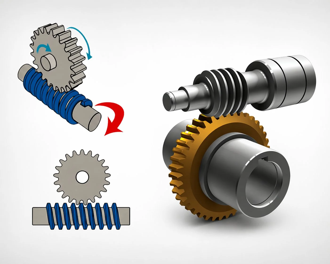
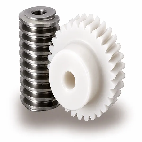
Šnekový převod je pravoúhlý přenos výkonu, kde válcová hřídel se závitem – šnek – pohání ozubené kolo, jehož zuby se šikmo ovíjejí po jeho obvodu. Každá otáčka šneku posune kolo o jeden zub, což znamená, že jednochodý šnek v záběru s kolem se 40 zuby poskytuje redukci 40:1 v jednom kompaktním stupni. Žádný jiný soukolí s rovnoběžnými hřídeli nedosahuje této hustoty převodu ve stejném rozsahu. Hlavní komponenty šnekového převodu se redukují na pouhé dvě konstrukční části: šnekový hřídel na vstupní straně a šnekové kolo na hnané straně.
Tento pohon se vyznačuje dvěma vlastnostmi. Zaprvé, šnek může volně pohánět kolo, ale kolo – u většiny geometrií s malým stoupáním – nemůže šnek pohánět zpět. Toto samosvorné chování je důvodem, proč se tyto pohony používají uvnitř kladkostrojů, výtahů, polohovačů antén a dopravníků, kde musí zátěž zůstat na místě i při výpadku napájení. Zadruhé, kontakt zubů je kluzný, což je tiché a tlumí vibrace, ale také důvod, proč je zde výběr mazání důležitější než u čelního ozubeného kola. Pochopení šneků a šnekových kol začíná tímto jediným pozorováním: kluzný, nikoli valivý kontakt, určuje veškeré chování pohonu.
Stručná poznámka k terminologii. Pojmy „šnekový pohon“ a „šnekové kolo“ se v inženýrské praxi používají zaměnitelně, zatímco „šneková převodovka“ nebo „šnekový reduktor“ označuje kompletní utěsněnou sestavu, která zahrnuje dvojici šneku a kola plus skříň, ložiska a prodloužení hřídele. Náš katalog zahrnuje všechny tři kategorie – volné komponenty, kompletní reduktory a převodovky připravené k motoru – takže korejští výrobci originálního vybavení (OEM) mohou nakupovat na jakékoli úrovni integrace, která vyhovuje jejich montážní lince.
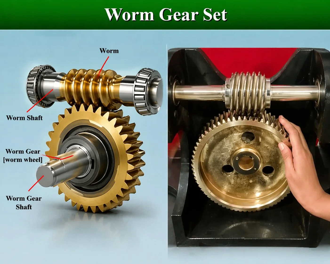
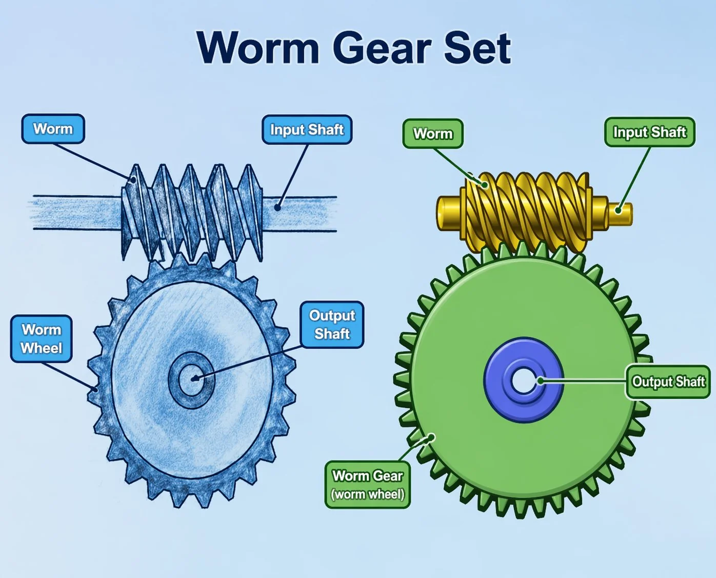
Anatomie v kostce
Najeďte myší na očíslované aktivní body na fotografii a zobrazí se název každého prvku. Čtyři popisky zahrnují prvky, které jsou na výkresech pro první ročník nejčastěji chybně identifikovány – zejména úhel stoupání, který je nakreslen na šneku, ale měřen jako sklon spirály vzhledem k radiální rovině hřídele.
Samosvorná vlastnost
Malé úhly stoupání (pod ~5°) vytvářejí dostatečně vysoké statické tření, aby kolo nemohlo pohánět šnek zpět. To je bezpečnostní prvek u výtahů a technický kompromis u efektivních pohonů – obvykle nelze mít obojí ve stejné sadě.
Bezhrdlové, jednohrdlové a dvouhrdlové šnekové převody.
Tři geometrie – různé nejčastěji specifikované typy šnekových převodů – pokrývají téměř všechny dnes používané pohony: bezhrdlové, jednohrdlové a dvouhrdlové. Volba mezi nimi je dána hlavně tím, jak moc zuby kola ovíjejí šnek – větší ovíjení znamená více párů zubů v kontaktu v daném okamžiku, což zvyšuje nosnost na úkor složitosti obrábění. Hrubé pravidlo, které dáváme korejským zákazníkům, kteří šnekový převod používají poprvé: bezhrdlové převody zvolte pro levné lehké pohony, jednohrdlové pro průmyslové práce a dvouhrdlé pouze tehdy, když je rozhodujícím faktorem hustota točivého momentu.
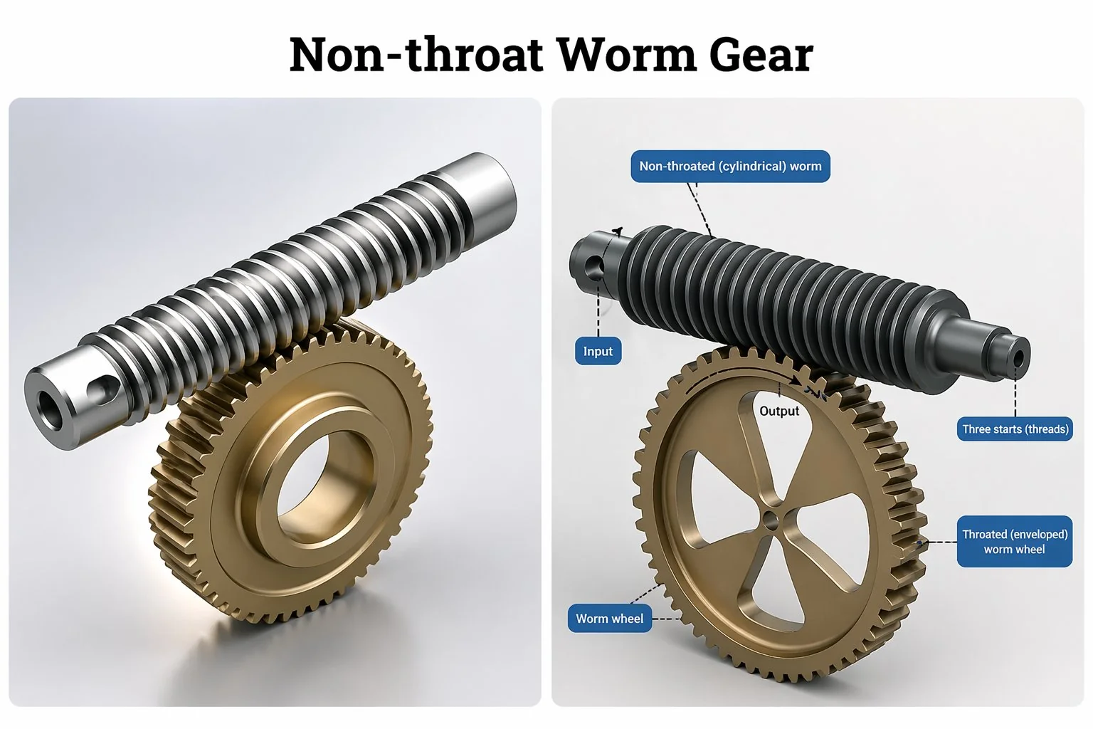
Šnekové převody bez hrdla
Válcový šnek zabírající s válcovým kolem – čelo kola je rovné, bez vybrání kolem šneku. V daném okamžiku zabírá pouze jeden nebo dva zuby, takže nosnost je ze tří typů nejnižší, ale nástroje jsou jednoduché a náhradní kola se snadno řežou.
Typické: lehké indexování, pohony přístrojů, kancelářská elektronika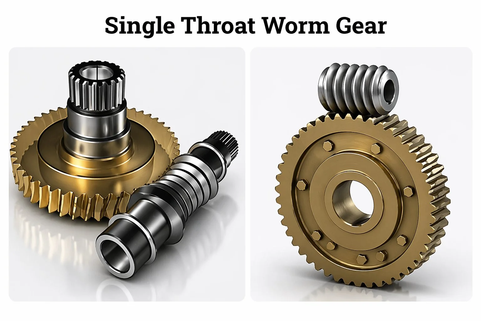
Jednohrdlové šnekové převody
Šnek zůstává válcový, ale kolo je odvalováno s konkávním hrdlem, které se částečně ovíjí kolem šneku. V každém okamžiku jsou v záběru tři až čtyři zuby – kontaktní vzor je spíše krátká čára než bod. Jedná se o typ šnekového převodu, který nejčastěji uvidíte v průmyslových reduktorech, pohonech zdvihacích zařízení a aplikacích s osou C obráběcích strojů.
Typické: průmyslové reduktory, pohony kladkostrojů, CNC osa C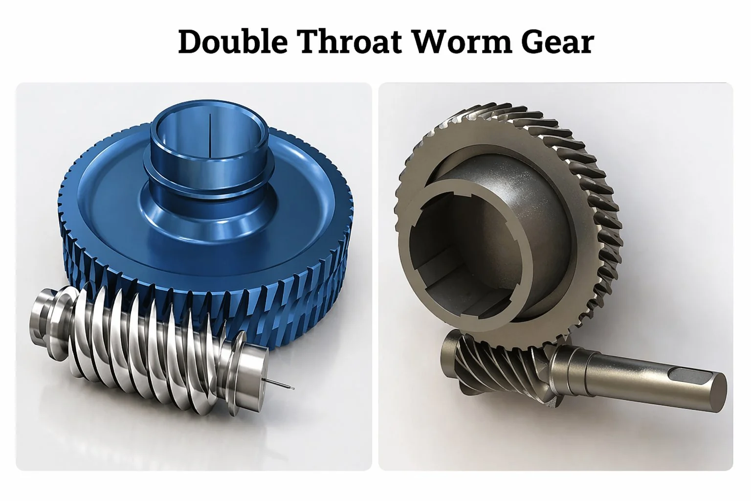
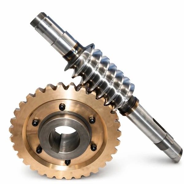
Dvouhrdlové (dvojitě obalující) šnekové převody
Šnek i kolo mají hrdlo – šnek má tvar přesýpacích hodin, které se ovíjejí kolem zubů kola. Současně zabírá šest až osm zubů. Nosnost na jednotku obálky je dvojnásobná až trojnásobná oproti sadě s jedním hrdlem. Nevýhodou je, že obrábění vyžaduje specializovanou odvalovací frézu pro každý převod, takže se zvyšují dodací lhůty i jednotkové náklady.
Typické: těžké kladkostroje, armáda, servopohony s vysokým točivým momentemJak fungují šnekové převody – krok za krokem.
Šnekový pohon převádí rotační vstup na hřídeli šneku na pomalejší rotační výstup s vyšším točivým momentem na šnekovém kole. Protože osy šneku a kola svírají vůči sobě úhel 90°, přenos pohybu také mění směr hřídele v jednom kroku. Níže uvedený pětikrokový návod je vysvětlením pro práci v dílně, které naše technické oddělení používá, když se nový korejský zákazník ptá, jak šnekové převody fungují v praxi, a nikoli v teorii.
Vstup na šnekové hřídeli
Motor, ruční kolo nebo předřazené ozubené kolo otáčí šnek jmenovitými otáčkami – u průmyslových pohonů obvykle 500–3000 ot/min.
Závit zabírá do zubu kola
Každá otáčka šneku posune jeden zub šnekového kola u jednochodého šneku, o dva zuby u dvouchodého šneku a tak dále.
Posuvný kontakt přenáší sílu
Kontakt mezi bokem šneku a zubem kola je primárně kluzný, a proto šnekové převodovka potřebuje speciální mazací obal – ne stejný olej jako čelní reduktor.
Násobení točivého momentu na kole
Výstupní točivý moment se zhruba škáluje s převodovým poměrem mínus ztráty třením. Souprava 40:1 s účinností 85 % dodává 34násobek vstupního točivého momentu na kole.
Samosvorné udrží zátěž
Když se vstupní napájení zastaví, šnek s mělkým vedením nemůže být zpětně poháněn zatížením kola – pohon drží polohu bez brzdy.
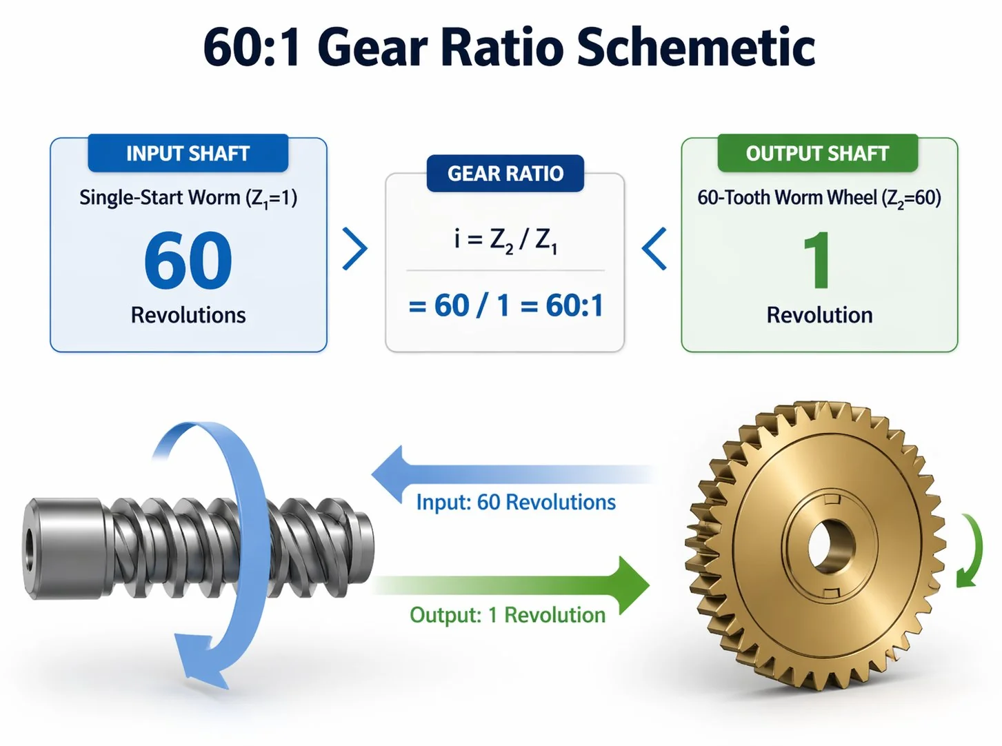
Převodový poměr šnekového převodu a výpočet
Převodový poměr šnekového kola se určuje jedinou rovnicí: redukční poměr = počet zubů šnekového kola ÷ počet začátků závitu šneku. Vyzkoušejte níže uvedenou živou kalkulačku – změňte kterékoli číslo a převod se okamžitě aktualizuje. Inženýři ji často používají k ověření správnosti cenové nabídky před vypracováním rozpočtu na pouzdro.
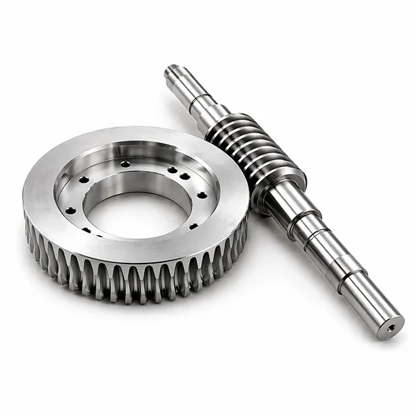
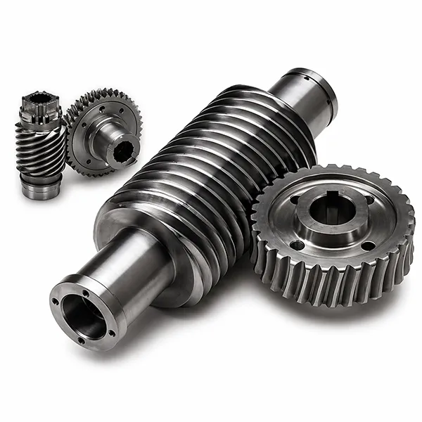
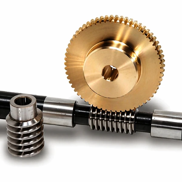
Dvě poloviny jakékoli sady šnekových převodů.
Každý pohon tohoto druhu, bez ohledu na výrobce nebo katalogovou velikost, se redukuje na dvě konstrukční komponenty: šnek (nazývaný také šnekový hřídel nebo hnací šroub) a šnekové kolo (nazývané také šnekové kolo). Správné určení dvojice je základem celé konstrukční hry – dimenzování jednoho bez druhého téměř vždy vede k pohonu, který běží hlučně nebo se rychle opotřebovává. Pracně osvojené pravidlo z našeho konstrukčního oddělení: nejprve specifikujte kolo (materiál, počet zubů, třída přesnosti) a poté odvodte geometrii šneku ze specifikace kola, nikoli naopak. Tento přístup udržuje kolo – součást, která se opotřebovává a vyměňuje – v rámci standardních katalogových velikostí, což zkracuje dodací lhůtu pro výměnu na polovinu během životnosti pohonu.
01Šnek (šnekový hřídel)
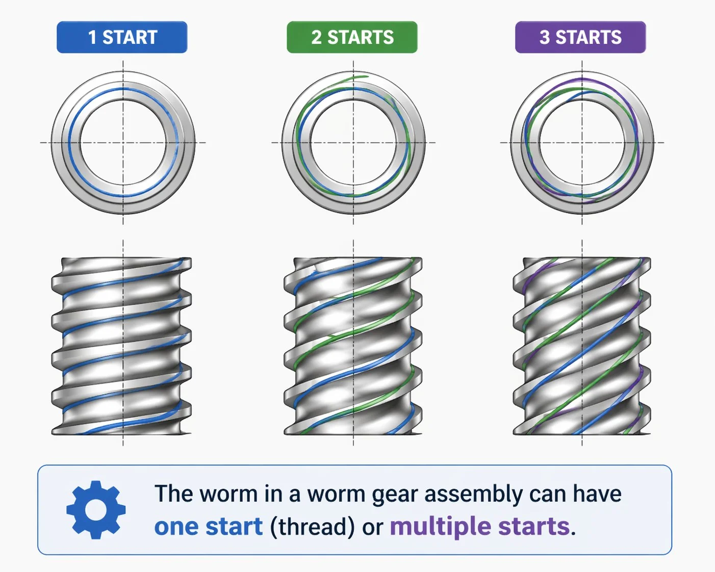
Válcová hřídel obrobená s jedním, dvěma, třemi nebo čtyřmi šroubovicovými závity – nazývanými „závity“. Počet závitů určuje poměr spolu s počtem zubů kola. Standardem pro hřídel je kalená legovaná ocel (SCM415, 20CrMnTi), protože kluzný kontakt vyžaduje tvrdý bok, aby se zabránilo oděru.
- MateriálSCM415 / 20CrMnTi
- Tvrdost58–62 HRC (pouzdro)
- Dostupné starty1, 2, 3, 4
- Povrchová úpravaRa 0,4 µm (bruse)
02Šnekové kolo
Hnané kolo se šikmými zuby, které odpovídají šroubovici šneku. Bronz je tradiční materiál kol, protože je měkčí než kalený šnek – měkčí materiál absorbuje kluzné opotřebení, což umožňuje opakovaně použít drahou kalený hřídel i při několika výměnách kol. V úzkém použití jsou běžná také kola z legované oceli a plastu.
- MateriálCínový bronz / Al-Fe bronz
- Tvrdost65–90 HB
- Počet zubůStandard Z20 – Z120
- Stupeň přesnostiDIN 5 – DIN 7
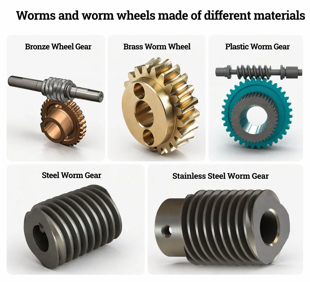
Z jakých materiálů se vyrábějí šnekové převody?
Pět materiálových skupin pokrývá téměř každé používané šnekové kolo. Zkušení inženýři dodržují pravidlo párování: tvrdá šneková hřídel na měkčím šnekovém kole s poměrem tvrdosti zhruba 2:1. Měkčí kolo absorbuje kluzné tření a přednostně se opotřebovává, což chrání dražší kalený šnekový hřídel po několik životností kola.
| Materiál šnekových a kolových kol | Nosnost | Odolnost proti korozi | Nejlepší padnutí |
|---|---|---|---|
| Kolo z cínu a bronzu + červ z legované oceli | Všeobecné průmyslové pohony, obráběcí stroje | ||
| Hliníkovo-železobronzové kolo + šnek SCM415 | Zvedáky, těžké dopravníky, nepřetržitá služba | ||
| Kolo z nerezové oceli 316 + šnek z nerezové oceli 304 | Potraviny, farmaceutický průmysl, mořské prostředí | ||
| Kolo z tvárné litiny + šnek 40Cr | Těžké pomalé jízdy (cement, těžba) | ||
| Nylonové kolo PA66 + šnek POM | Kancelářská elektronika, mikropřístroje |
Délky tyčí jsou relativní skóre oproti nejsilnější možnosti ve stejném sloupci; nikoli absolutní technické hodnoty.
Každá sada šnekových převodů, kterou uvádíme v katalogu, je k dispozici v minimálně třech z těchto materiálových párů jako standardní objednávka – zakázkové párování mimo tento seznam se naceňuje individuálně s technickým posouzením. Pro velkoobjemové výrobní programy může naše metalurgické oddělení také získat zakázkové bronzové slitiny z korejských a japonských sléváren, pokud specifikace vyžaduje něco nad rámec standardních katalogových jakostí.
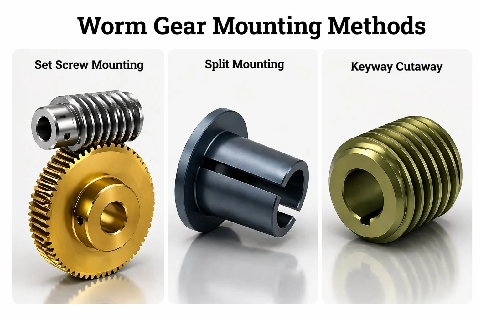
Způsoby montáže šnekového převodu – drážka pro pero, stavěcí šroub, dělená převodovka.
Šnekové kolo lze upevnit na hřídel jednou ze tří standardních metod montáže – drážkou pro pero, stavěcím šroubem nebo děleným nábojem. Volba je dána hlavně přenášeným krouticím momentem, přístupem k montáži a tím, jak často je třeba kolo během provozu demontovat. Inženýři často řeší otázku montáže až po výběru materiálového páru – tři níže uvedené metody zvládají každá jinou kombinaci zatížení a provozuschopnosti.
Klínová drážka
Obdélníková drážka vyříznutá jak v hřídeli, tak v otvoru kola je osazena odpovídajícím ocelovým perem. Pero přenáší veškerý krouticí moment smykem – mezi otvorem a hřídelí nedochází k žádnému tření. Jedná se o metodu montáže s nejvyšším dostupným krouticím momentem a také o metodu, která snáší největší tepelné cykly. Nevýhodou je, že demontáž kola s perem po letech provozu může být obtížná, pokud otvor zkorodoval na hřídeli.
Stavěcí šroub
Závitový spojovací prvek procházející nábojem kola dosedá na plošku vyfrézovanou do hřídele. Točivý moment se přenáší třením a zářezem, který šroub vytvoří v plošce hřídele. Tato metoda je levná a rychlá na instalaci a náboj nevyžaduje drahé protahování drážky pro pero – proto dominuje v katalogových šnekových kolech pro malé pohony.
Dělený náboj (svorka)
Náboj kola je radiálně rozříznutý a uzavřený kolem hřídele dvěma nebo čtyřmi upínacími šrouby. Není nutné žádné obrábění hřídele – kolo se umisťuje čistě třením. Změna polohy je snadná, což z děleného náboje dělá preferovanou volbu u prototypů a malosériových strojů, kde se konstrukce stále může opakovat. Upínací síla vyžaduje větší průměr náboje, takže dělený náboj není vždy správným řešením v těsných prostorách.
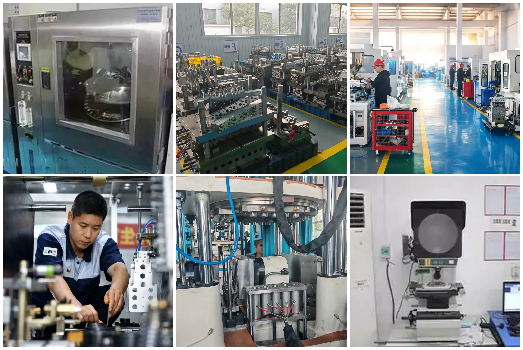
Proč korejští výrobci originálních dílů (OEM) směrují objednávky šnekových převodů přes Ansan.
Společnost Korea Ever-Power Worm And Worm Wheel Co., Ltd. provozuje specializovanou výrobní linku na šneková ozubená kola a převodovky v průmyslové zóně Ansan. Zařízení je specializované – z těchto linek se nevyrábějí žádná čelní ani šikmá ozubená kola – což zajišťuje hluboké technické znalosti a krátkou dobu nastavení mezi katalogovými velikostmi. Čtyři věci odlišují provoz v Ansanu od větších japonských dodavatelů první úrovně, se kterými se korejští kupující obvykle srovnávají.
Položky z katalogu se odesílají do 25 pracovních dnů – o 60 % kratší dobu než 8týdenní japonský průměr 1. úrovně při ekvivalentních specifikacích
prototypové série od 2 kusů, výroba od 10 kusů – užitečné, když zákazník stále iteruje návrh
kompletní sortiment vyráběný ve vlastní firmě; otočný stůl broušený v jakosti DIN 5 po tepelném zpracování na profilové brusce Reishauer
vypracování recenzí a cenových nabídek v korejštině do jednoho pracovního dne; podpora také v japonštině a angličtině
Společnost Ever-Power je registrována jako Korea Ever-Power Worm And Worm Wheel Co., Ltd. na adrese Sandan-ro, Danwon-gu, Ansan-si, Gyeonggi-do. Výrobní hala používá systém jakosti ISO 9001:2015 s postupy v souladu s normou IATF 16949 pro automobilové programy úrovně 1. Kontaktujte technické oddělení na adrese [email protected] – výkresy jsou před odesláním cenové nabídky zkontrolovány v souladu s dohodou o mlčenlivosti.
Doporučené produkty se šnekovými převody.
Šest níže uvedených vlajkových produktů šnekových převodů pokrývá nejprodávanější kategorie řady Ansan – nerezové převody pro CNC, legované oceli pro automobilový průmysl, duplexní převody pro přesnost s nulovou vůlí, válcové převody pro všeobecný průmysl, mosazné převody pro mikroaplikace a plastové převody pro pohony přístrojů. Každá karta odkazuje na kompletní stránku produktu s tabulkou parametrů, možnostmi materiálů a podrobnostmi o poptávce.
Šnekové převodovky z nerezové oceli
Přesnost DIN 5–DIN 7 pro CNC otočné stoly a pohony osy C obráběcích strojů. Nerezová ocel 304/316 pro korozivní prostředí.
Šnekové a ozubené kolo z legované oceli
SCM415 / 20CrMnTi cementovaná a broušená ocel pro programy EPS, EPB a sedlových aktuátorů. V souladu s normou IATF 16949.
Dvojitá šneková převodovka
Axiálně posuvný šnek s proměnnou tloušťkou zubu eliminuje vůli o 30–40 stupňů % oproti standardním katalogovým sadám.
Válcové šnekové kolo
Jednohrdlová válcová dvojice, průmyslový pracant – bronz na oceli pro 80 % pro všeobecné použití v pohonech.
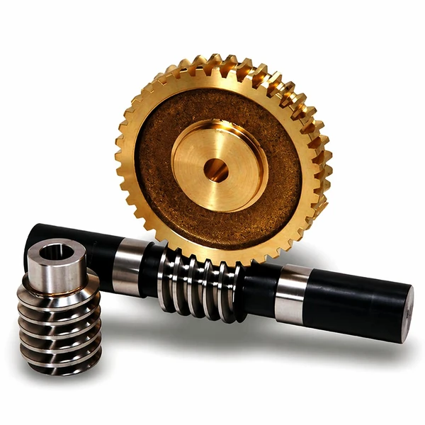
Mosazné šnekové kolo a hřídel
Mosazné kolo z mikromodulu s odpovídající ocelovou šnekovou hřídelí pro pohony přístrojů, kancelářskou elektroniku a lékařské přístroje.
Plastové šnekové převody
Kola z POM a PA66 technické kvality pro tichý chod a aplikace s nízkým zatížením – kancelářské vybavení, hračky, spotřební zboží.
Kde se uplatňují šnekové převody.
Běžné aplikace šnekových převodů sahají do všech oblastí průmyslového života – všude tam, kde konstrukce vyžaduje velké snížení v malém objemu, tichý provoz nebo schopnost udržet zátěž bez brzdy. Čtyři níže uvedené průmyslové panely pokrývají zhruba 70 pohonů typu %, které od společnosti Ansan dodáváme každý čtvrtletí. Kromě těchto čtyř dodáváme také pravidelné objemy do lékařských zobrazovacích zařízení, osvětlovacích souprav pro operační sály, pohonů pro otáčení a náklon větrných turbín, aktuátorů solárních sledovačů a profesionálních vysílacích otočných a naklápěcích hlavic – to vše v aplikacích, kde kombinace vysokého převodového poměru, tichého provozu a samosvornosti jednoduše nemůže být srovnána s konkurenční řadou převodů.
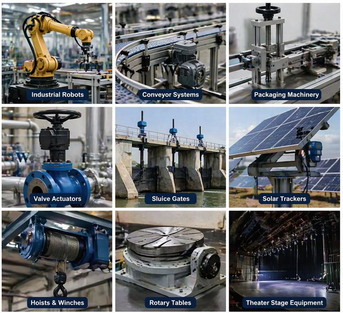
Elektrický posilovač řízení, motory sklápění sedadel, pohony stěračů, aktuátory parkovací brzdy – zde dominuje dvojice 20CrMnTi-na-bronzu, obvykle s přesností DIN 6 a dokumentací IATF 16949.
5osé otočné stoly, zásobníky ATC, pohony osy C na CNC soustruzích – přesnost DIN 5 až DIN 7 v závislosti na poloze. Broušené zuby na kole jsou standardem pro provoz s otočným stolem.
Samosvorné šnekové pohony drží zátěž při výpadku napájení – eliminují tak samostatnou brzdu, kterou by pohon se šroubovým ozubeným kolem potřeboval. Charakteristickým prvkem je jednochodý šnek s úhlem stoupání menším než 5°.
Nízké otáčky a tichý chod dělají ze šnekového převodu standardní volbu pro balicí linky a dopravníky na potraviny. Pro kompatibilitu s omyvatelným povrchem je preferována dvojice nerezových materiálů.
Výhody, omezení a mazání.
Každá řada převodů s sebou nese kompromisy. Tyto pohony jsou v některých případech vynikající, v jiných jsou skutečně špatnou volbou. Níže uvedená poctivá bilance je to, čím naše technické oddělení provede korejské konstruktéry během prvního hovoru se specifikací. Doporučujeme si před závazným návrhem projít oba sloupce – polovina žádostí, které začínají poptávkou jako „potřebujeme šnekové kolo“, nakonec lépe obslouží spirálový nebo planetový stupeň, a když to řekneme, krátkodobě to stojí prodej, ale buduje se důvěra, která nám v příštích třech letech vygeneruje pět opakovaných objednávek.
Výhody šnekových převodů
- Velké snížení v jedné fázi. 20:1 až 300:1 bez nutnosti stohování planetárních stupňů.
- Samosvorná schopnost. Udrží zátěž bez samostatné brzdy, pokud je úhel stoupání menší než přibližně 5°.
- Uspořádání hřídele 90°. Mění směr a snižuje rychlost ve stejné součásti.
- Tiché a plynulé. Kluzný kontakt produkuje nižší hluk než jakákoli alternativa s paralelním hřídelem.
- Tlumení nárazů. Kluzné rozhraní funguje jako tlumič cyklických točivých momentů.
- Kompaktní obálka. Hustota poměru na jednotku objemu je nejvyšší ze všech rodin ozubených kol.
Omezení šnekových převodů
- Nižší účinnost. Kluzný kontakt ztrácí 10–50 % % v závislosti na převodovém poměru a mazání – mnohem více než u čelního nebo spirálového kontaktu.
- Generování tepla. Stejné kluzné pohyby, které zajišťují tichý chod, zároveň produkují teplo, které musí být odváděno olejem.
- Není reverzibilní (záměrně). Samosvornost je sice funkcí, ale znamená to, že kolo nemůže pohánět šnek v sadě s malým stoupáním.
- Citlivé na mazivo. Šnekové pohony vyžadují specializované převodové oleje – typicky se používají syntetické oleje ISO VG 220 nebo 460; standardní hydraulický olej nestačí.
- Opotřebení kol je omezujícím faktorem životnosti. Měkčí bronzové kolo se opotřebovává přednostně – počítejte s tím, že kolo budete muset jednou nebo dvakrát vyměnit během životnosti šnekového hřídele.
- Jednotková cena za Nm. Pro stejný výstupní točivý moment je spirálový stupeň obvykle o 15–30 % levnější než šnekový pohon.
Mazání šnekových převodů v kostce
Výběr mazání šnekového převodu závisí na teplotě olejové vany, otáčkách šneku a zatížení. Níže uvedená tabulka ukazuje stupeň ISO VG, který naše technické oddělení obvykle doporučuje pro každou kombinaci – považujte jej za výchozí bod, nikoli za konečnou specifikaci. Pohony pracující mimo tyto podmínky nebo pohony s neobvyklými pracovními cykly si zaslouží individuální kontrolu mazání před první náplní oleje. Volba správného stupně viskozity je nejdůležitějším rozhodnutím o životnosti jakéhokoli šnekového převodu – nesoulad dvou stupňů může snížit očekávanou životnost ložiska a hřbetu na polovinu.
| Teplota jímky | Nízké zatížení (≤30 %) | Střední zatížení | Těžké zatížení (≥80 %) |
|---|---|---|---|
| Pod 40 °C | ISO VG 150 | ISO VG 220 | ISO VG 320 |
| 40 – 70 °C | ISO VG 220 | ISO VG 320 | ISO VG 460 |
| 70 – 90 °C | ISO VG 320 | ISO VG 460 | Syntezátor ISO VG 680 |
| Nad 90 °C | Syntezátor ISO VG 460 | Syntezátor ISO VG 680 | Nucené chlazení |
Pro teploty olejové vany nad 70 °C jsou vhodnější syntetické polyalfaolefinové (PAO) nebo polyglykolové (PAG) oleje – minerální oleje v tomto rozsahu příliš rychle oxidují. Polyglykolové oleje vykazují mírně nižší tření při kluzném kontaktu a mohou prodloužit životnost o 30–50 °C při zvýšené teplotě, ale nejsou kompatibilní s každým materiálem těsnění – před dodatečnou montáží PAG do pohonu původně určeného pro minerální olej se poraďte s naším technickým oddělením.
⚠Tři běžné režimy selhání, na které je třeba dávat pozor
Znalost toho, jak tyto disky selhávají, je polovinou úspěchu při navrhování takového, který vydrží. Tři níže uvedené režimy selhání představují zhruba 85 vrácení zboží v rámci záruky % u naší korejské zákaznické základny – jejich včasné rozpoznání umožňuje týmu údržby naplánovat plánovanou výměnu namísto nouzového zastavení linky.
Malé povrchové důlky z opakovaného kontaktního namáhání. Očekává se to po dlouhou dobu životnosti; pokud se objeví brzy, pohon je přetížený nebo je mazací film příliš tenký.
Podélné vrypy v důsledku krátkodobého kontaktu kovu s kovem. Způsobeno nedostatkem maziva, nesprávnou viskozitou nebo kontaminací.
Náhlé katastrofické selhání. Způsobeno rázovým přetížením nebo únavou materiálu po delším provozu mimo dimenzovaný provozní faktor.
Jak vybrat správný šnekový převod – v sedmi otázkách.
Sedm níže uvedených otázek pokrývá všechny informace, které naše technické oddělení potřebuje k vytvoření cenové nabídky na šnekové soukolí nebo šnekovou převodovku. Projděte si je před prvním e-mailem – tím se obvykle zkrátí cyklus cenové nabídky ze čtyř dnů na méně než jeden.


