Katukma ulod ug ulod nga ligid gidesinyo para sa industriya sa Korea.
Ang Korea Ever-Power Worm And Worm Wheel Co.,Ltd naggama og kompletong katalogo sa mga worm drive component — gikan sa Ø5 mm micro-modules ngadto sa Ø300 mm industrial worm wheels — nga gipadala gikan sa Ansan ngadto sa mga OEM sa tibuok Korea, Japan ug Southeast Asia sukad niadtong 2015.
Unsa gyud diay ang mga worm gears?
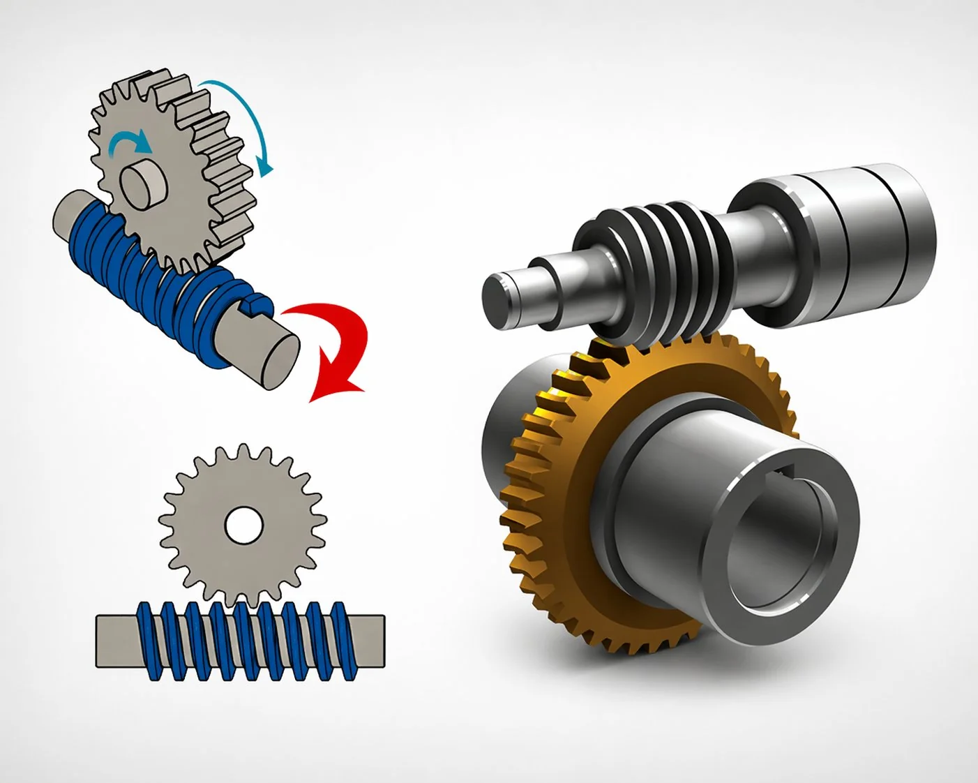
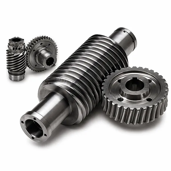
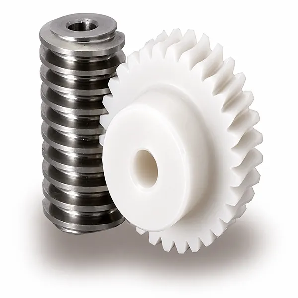
Ang worm gear usa ka right-angle power transmission diin ang usa ka threaded cylindrical shaft — ang worm — nagduso sa usa ka ligid nga may ngipon kansang mga ngipon naglibot sa palibot niini. Ang matag liko sa worm mopaabante sa ligid pinaagi sa usa ka ngipon, nga nagpasabot nga ang single-start worm meshing nga adunay 40-tooth wheel makahatag og 40:1 nga pagkunhod sa usa ka compact stage. Walay laing parallel-shaft gearing nga makab-ot nianang ratio density sa samang envelope. Ang mga nag-unang component sa usa ka worm gear system mokunhod ngadto sa duha na lang ka engineered parts: ang worm shaft sa input side, ug ang worm wheel sa driven side.
Duha ka kinaiya ang nagpalahi niining drive. Una, ang worm gawasnon nga makapadagan sa ligid, apan ang ligid — sa kadaghanan sa mga shallow-lead geometries — dili maka-back-drive sa worm. Kining self-locking nga kinaiya mao ang nagbutang niining mga drive sulod sa mga hoist, lift, antenna positioner ug conveyor diin ang load kinahanglan magpabilin kung ang kuryente mapalong. Ikaduha, ang tooth contact usa ka sliding contact, nga hilom ug vibration-damping apan mao usab ang hinungdan ngano nga ang pagpili sa lubrication mas importante dinhi kaysa sa spur gear. Ang pagsabot sa mga worm ug worm wheel magsugod sa usa ka obserbasyon: ang sliding contact, dili ang rolling contact, ang nagdumala sa tanan bahin sa kinaiya sa drive.
Usa ka mubo nga nota sa terminolohiya. Ang "Worm drive" ug "worm gear" gigamit nga baylobaylo sa praktis sa inhenyeriya, samtang ang "worm gearbox" o "worm gear reducer" nagtumong sa usa ka kompleto nga selyado nga asembliya nga naglakip sa pares nga worm-and-wheel dugang sa housing, bearings ug shaft extensions. Ang among katalogo naglangkob sa tanan nga tulo ka kategorya — mga loose components, kompleto nga reducers, ug motor-ready gearboxes — aron ang mga Korean OEM makapalit sa bisan unsang lebel sa integrasyon nga mohaum sa ilang linya sa asembliya.
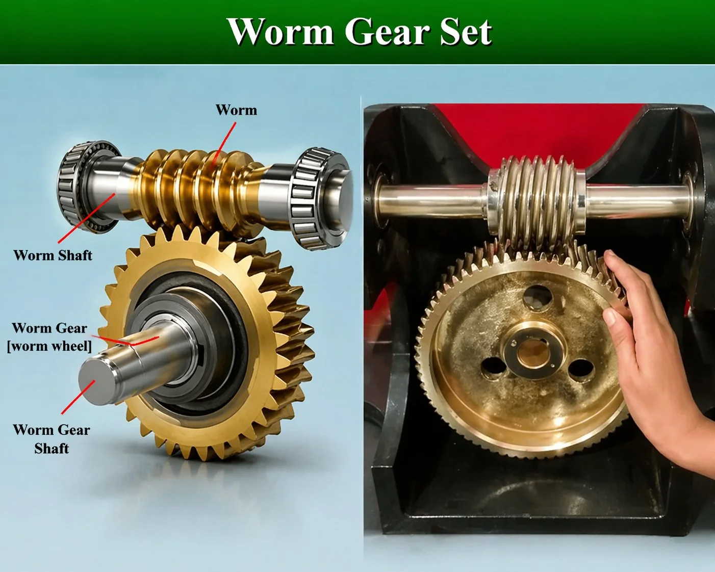
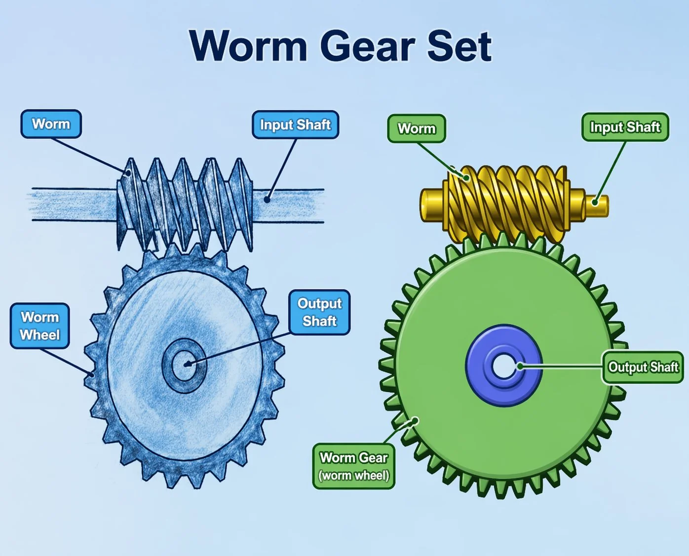
Anatomiya sa usa ka pagtan-aw
I-hover ang ginumero nga mga hotspot sa litrato aron makita ang ngalan sa matag bahin. Ang upat ka callout naglangkob sa mga elemento nga kanunay nga dili mailhan sa mga drowing sa unang tuig — labi na ang anggulo sa tingga, nga gidrowing sa worm apan gisukod isip bakilid sa spiral relatibo sa radial plane sa shaft.
Ang propiedad nga self-locking
Ang mabaw nga mga anggulo sa tingga (ubos sa ~5°) makamugna og static friction nga igo kataas nga ang ligid dili makabalik sa pagduso sa worm. Kini usa ka bahin sa kaluwasan sa mga lift ug usa ka engineering trade-off sa episyente nga mga drive — dili kasagaran nga pareho ang dili mahimo sa parehas nga set.
Mga gears sa worm nga dili tutunlan, usa ka tutunlan, ug doble nga tutunlan.
Tulo ka geometriya — ang lain-laing klase sa worm gears nga kasagarang gitino — naglangkob sa halos tanang drive nga gigamit karon: non-throat, single-throat, ug double-throat. Ang pagpili tali kanila nagdepende kon unsa ka dako ang pagputos sa mga ngipon sa ligid sa palibot sa worm — ang mas daghang pagputos nagpasabot nga mas daghang pares sa ngipon nga magkontak sa bisan unsang orasa, nga mopataas sa kapasidad sa karga apan moresulta sa pagkakomplikado sa machining. Usa ka lagda nga among gihatag sa mga bag-ong kustomer sa Korea: pilia ang non-throat para sa cost-driven light drives, single-throat para sa 80 % nga trabaho sa industriya, ug double-throat lamang kon ang torque density mao ang magdesisyon.
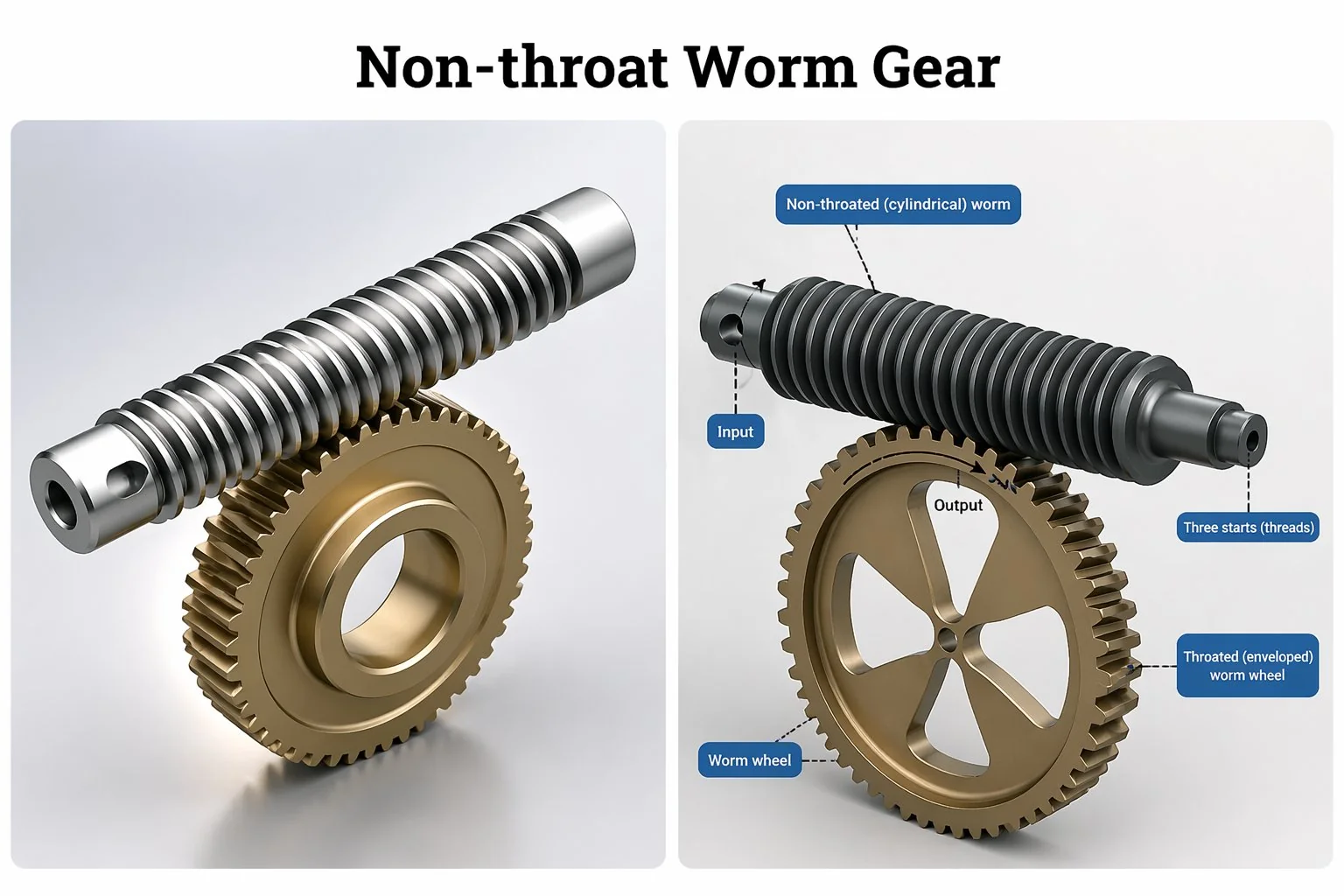
Mga gamit nga dili pangpatay sa ulod sa tutunlan
Silindrikong ulod nga nagdugtong sa silindrikong ligid — ang nawong sa ligid tul-id nga giputol, dili gilibutan sa ulod. Usa o duha ra ka ngipon ang mosangit sa bisan unsang orasa, mao nga ang kapasidad sa karga mao ang labing ubos sa tulo ka klase, apan ang paggamit og mga himan sayon ra ug ang pag-ilis sa mga ligid sayon putlon.
Kasagaran: light-duty indexing, instrument drives, office electronics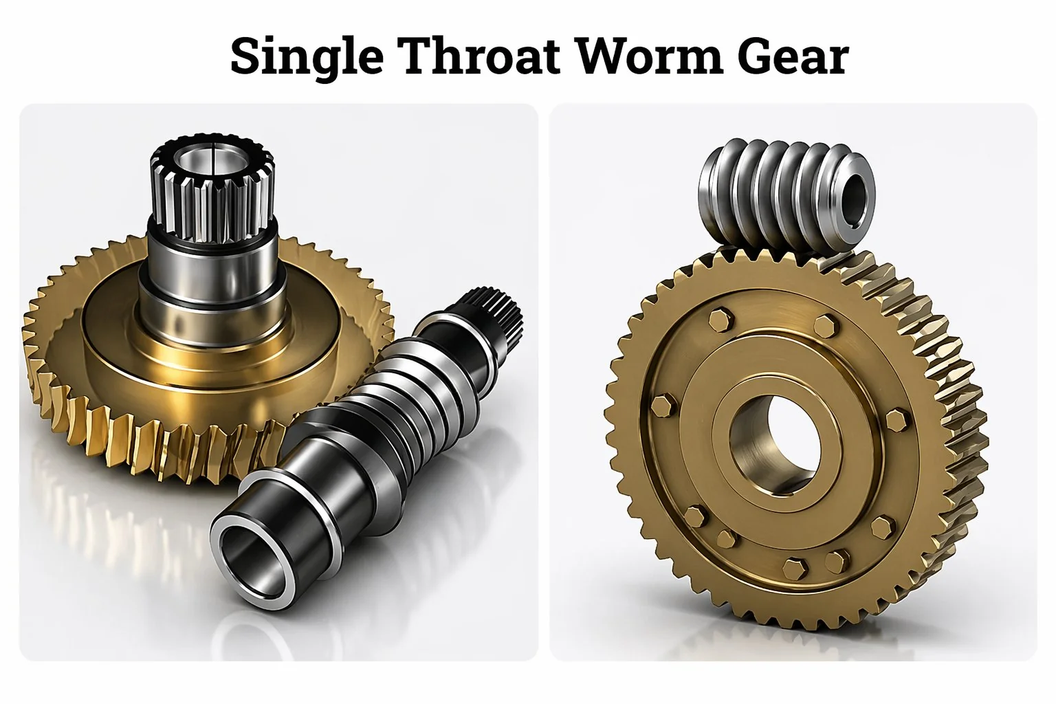
Mga gamit sa ulod nga single-throat
Ang ulod magpabilin nga silindro apan ang ligid gi-hobbed nga adunay concave nga tutunlan nga nagputos sa bahin sa ulod. Tulo ngadto sa upat ka ngipon ang motapot sa mesh bisan unsang orasa — ang contact pattern usa ka mubo nga linya imbes nga usa ka punto. Kini ang klase sa worm gear nga imong makita kanunay sa mga industrial reducers, hoist drives, ug machine-tool C-axis applications.
Kasagaran: mga industrial reducers, hoist drives, CNC C-axis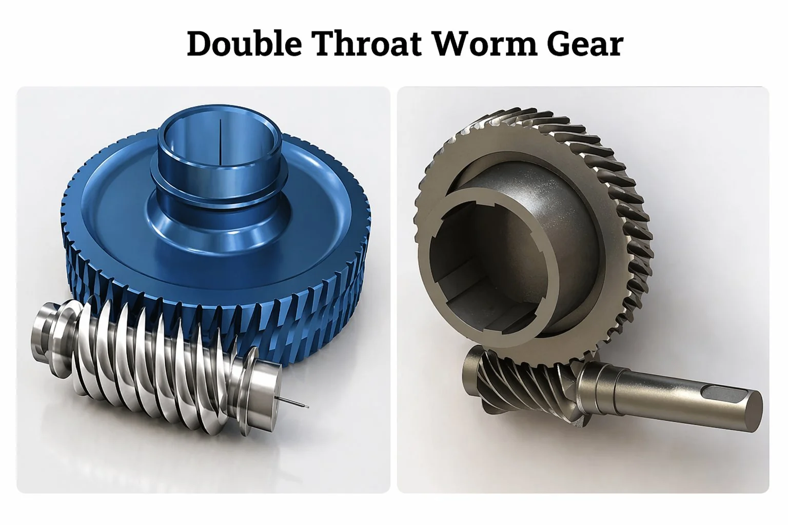
Doble-tuton (doble-nga nagtabon) nga mga gamit sa ulod
Ang ulod ug ang ligid parehong gi-throat — ang ulod moporma og hourglass nga molibot sa ngipon sa ligid. Unom ngadto sa walo ka ngipon ang dungan nga mo-engage. Ang kapasidad sa pagkarga kada unit envelope duha ngadto sa tulo ka pilo sa single-throat set. Ang trade-off: ang machining nanginahanglan og espesyal nga hob para sa matag ratio, busa ang lead time ug unit cost parehong mosaka.
Kasagaran: bug-at nga mga hoist, militar, high-torque servo driveGiunsa paglihok ang mga worm gear — lakang sa lakang.
Ang worm drive nag-convert sa rotary input sa worm shaft ngadto sa mas hinay ug mas taas nga torque rotary output sa worm wheel. Tungod kay ang worm ug wheel axes nahimutang sa 90° sa usag usa, ang motion transfer nag-usab usab sa direksyon sa shaft sa usa ka yugto. Ang lima ka lakang nga walkthrough sa ubos mao ang pagpasabut sa shop-floor nga gigamit sa among engineering desk kung ang usa ka bag-ong Korean nga kustomer mangutana kung giunsa paglihok ang mga worm gear sa praktis kaysa sa teorya.
Pag-input sa worm shaft
Ang motor, hand-wheel, o upstream gear mao ang mopaandar sa worm sa rated rpm niini — kasagaran 500 – 3000 rpm para sa mga industrial drive.
Ang hilo mosumpay sa ngipon sa ligid
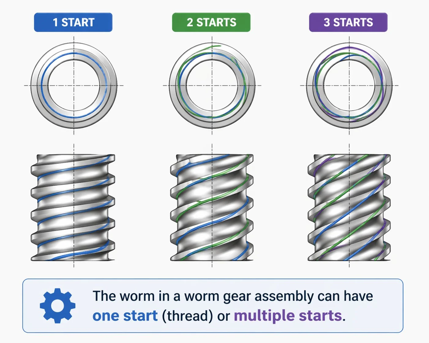
Ang matag pagtuyok sa ulod mopaabante og usa ka ngipon sa ligid sa ulod para sa usa ka single-start nga ulod, duha ka ngipon para sa usa ka double-start nga ulod, ug uban pa.
Ang kusog sa pagbalhin sa sliding contact
Ang pagkontak tali sa worm flank ug sa ngipon sa ligid kasagaran tungod sa pag-slide, mao nga ang worm gear nagkinahanglan og espesyal nga lubricant envelope — dili parehas nga lana sa spur reducer.
Pagpadaghan sa torque sa ligid
Ang output torque halos mosukod sa ratio nga gikuhaan og friction losses. Ang 40:1 set nga adunay 85 % efficiency mohatag og 34 × sa input torque sa ligid.
Ang self-locking mohawid sa karga
Kon mohunong ang input power, ang shallow-lead worm dili ma-back-drive sa karga sa ligid — ang drive magpabilin sa posisyon nga walay preno.
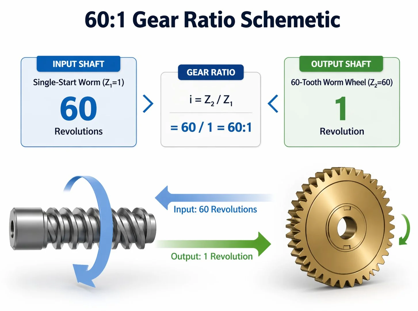
Ratio sa gear sa ulod ug kalkulasyon
Ang worm gear ratio gitino pinaagi sa usa ka equation: reduction ratio = ngipon sa worm wheel ÷ pagsugod sa hilo sa worm. Sulayi ang live calculator sa ubos — usba ang bisan hain nga numero ug ang reduction update dayon. Kanunay kini gamiton sa mga inhenyero aron susihon ang sanity-check sa usa ka quote sa dili pa magdrowing sa housing envelope.
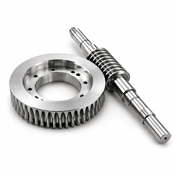
Ang duha ka katunga sa bisan unsang set sa worm gear.
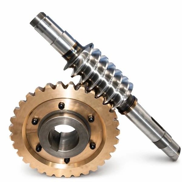
Ang matag drive nga ingon niini, bisan unsa pa ang gidak-on sa tiggama o katalogo, mahimong duha na lang ka engineered components: ang worm (gitawag usab nga worm shaft o drive screw) ug ang worm wheel (gitawag usab nga worm gear). Ang pagkuha sa husto nga pares mao ang tibuok nga dula sa disenyo — ang pag-dimensyon sa usa nga wala ang lain hapit kanunay nga moresulta sa usa ka drive nga saba nga modagan o dali nga madaot. Usa ka lisud nga lagda gikan sa among engineering desk: ipiho una ang ligid (materyal, ihap sa ngipon, klase sa katukma), dayon kuhaa ang geometry sa worm gikan sa espesipikasyon sa ligid imbes nga ang sukwahi. Kini nga pamaagi nagpabilin sa ligid — ang bahin nga madaot ug ilisan — sulod sa standard nga gidak-on sa katalogo, nga nagpamenos sa oras sa pag-ilis sa katunga sa kinabuhi sa serbisyo sa drive.
01Ang ulod (tumoy sa ulod)
Usa ka silindro nga shaft nga gimakina gamit ang usa, duha, tulo, o upat ka helical threads — gitawag nga "starts". Ang gidaghanon sa mga starts nagtakda sa ratio uban sa gidaghanon sa ngipon sa ligid. Ang gahi nga alloy steel (SCM415, 20CrMnTi) mao ang standard para sa shaft tungod kay ang sliding contact nanginahanglan ug gahi nga kilid aron malikayan ang pagkagusbat.
- MateryalSCM415 / 20CrMnTi
- Katig-a58–62 HRC (kaso)
- Anaa ang mga pagsugod1, 2, 3, 4
- Paghuman sa nawongRa 0.4 µm (gipatong)
02Ang ligid sa ulod
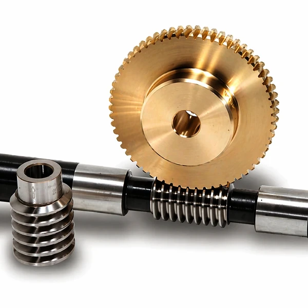
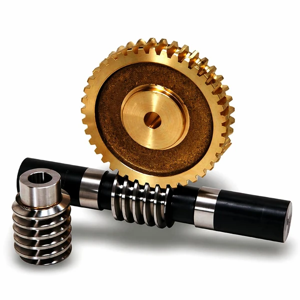
Ang gimaneho nga ligid nga adunay mga ngipon nga oblique nga mohaom sa helix sa ulod. Ang bronse mao ang tradisyonal nga materyal sa ligid tungod kay kini mas humok kay sa gahi nga ulod — ang mas humok nga materyal mosuhop sa sliding wear, nga naghimo sa mahal nga gahi nga shaft nga magamit pag-usab sa daghang mga pag-ilis sa ligid. Ang alloy steel ug plastik nga mga ligid komon usab sa niche duty.
- MateryalBronse nga lata / Bronse nga Al-Fe
- Katig-a65–90 HB
- Ihap sa ngiponZ20 – Z120 nga estandard
- Grado sa katukmaDIN 5 – DIN 7
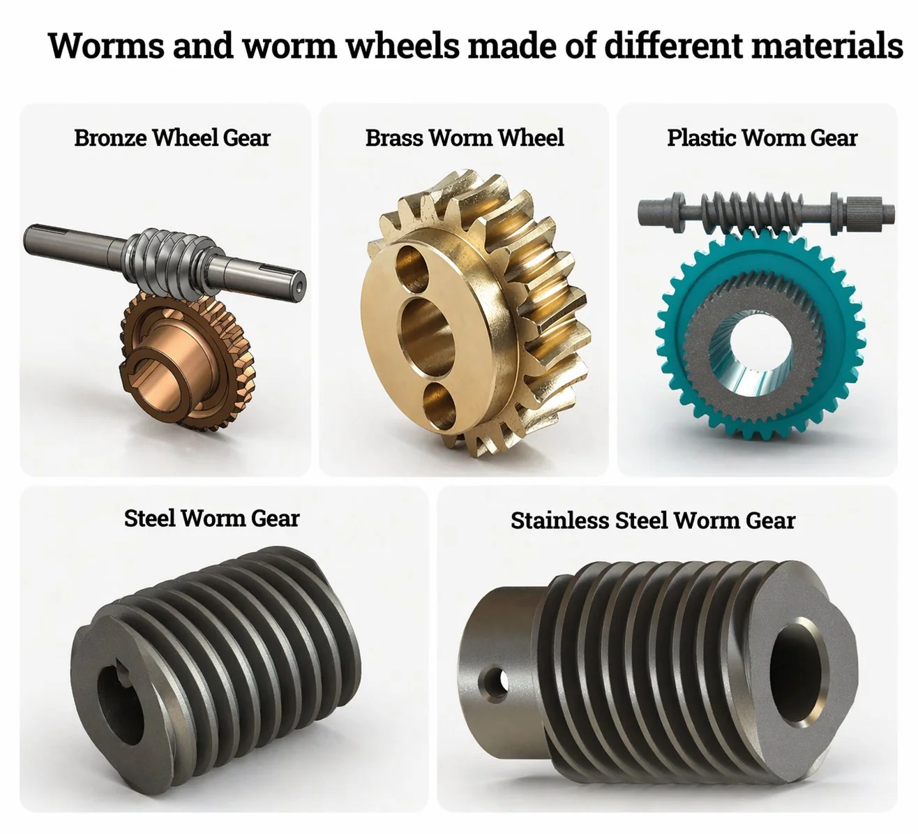
Unsang mga materyales ang gihimo sa mga worm gear?
Lima ka pamilya sa materyal ang motabon sa halos tanang worm gear nga gigamit. Ang lagda sa pagpares nga gisunod sa mga eksperyensiyadong inhenyero: gahi nga worm shaft sa mas humok nga worm wheel, nga adunay hardness ratio nga gibana-bana nga 2:1 tali sa duha. Ang mas humok nga ligid mosuhop sa sliding friction ug mas dali nga madaot, nga manalipod sa mas mahal nga gahi nga worm shaft sa daghang kinabuhi sa serbisyo sa ligid.
| Materyal sa Worm ug Wheel | Kapasidad sa pagkarga | Pagsukol sa kaagnasan | Labing haom |
|---|---|---|---|
| Ligid nga bronse nga lata + ulod nga asero nga haluang metal | Kinatibuk-ang mga pang-industriya nga drive, mga gamit sa makina | ||
| Ligid nga aluminyo-puthaw nga bronse + ulod nga SCM415 | Mga hoist, bug-at nga conveyor, 24/7 nga duty | ||
| Stainless 316 nga ligid + stainless 304 nga ulod | Pagkaon, parmasyutiko, ug mga palibot sa dagat | ||
| Ductile cast iron wheel + 40Cr worm | Hinay kaayo nga pagmaneho (semento, pagmina) | ||
| PA66 naylon nga ligid + POM worm | Mga elektroniko sa opisina, mga mikro-instrumento |
Ang gitas-on sa bar kay relatibong pag-iskor batok sa pinakakusog nga kapilian sa samang kolum; dili absolutong mga bili sa inhenyeriya.
Ang matag catalog worm gear set nga among gilista anaa sa labing menos tulo niining mga pares sa materyal isip standard order — ang custom pairings gawas niini nga lista gikutlo nga tagsa-tagsa uban ang engineering review. Alang sa mga programa sa produksiyon nga taas og volume, ang among metallurgy desk mahimo usab nga makakuha og custom bronze alloys gikan sa mga foundry sa Korea ug Hapon kung ang espesipikasyon nanginahanglan og labaw pa sa standard catalog grades.
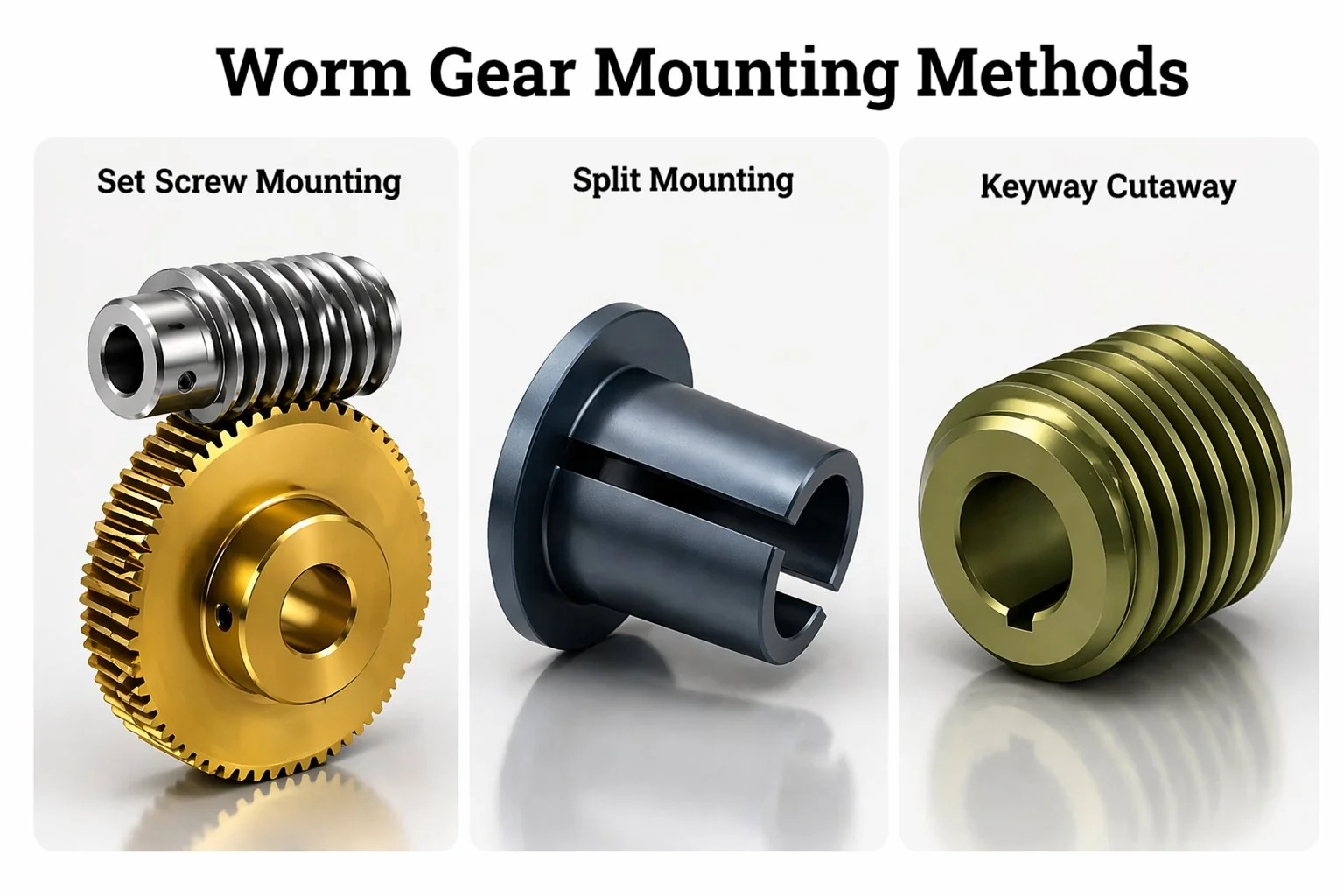
Mga pamaagi sa pag-mount sa worm gear — keyway, set screw, split.
Ang usa ka worm wheel mahimong ikabit sa iyang shaft pinaagi sa usa sa tulo ka standard nga pamaagi sa pag-mount — keyway, set screw, o split hub. Ang pagpili nagdepende sa transmitted torque, assembly access, ug kung unsa ka subsob kinahanglan nga tangtangon ang ligid samtang gigamit. Kasagaran, ang mga inhenyero mohusay sa pangutana sa pag-mount human mapili ang pares sa materyal — ang tulo ka pamaagi sa ubos matag usa nagdumala sa lainlaing kombinasyon sa karga ug pagka-serbisyo.
Keyway
Ang rektanggulo nga lungag nga giputol sa shaft ug sa wheel bore makadawat og parehas nga steel key. Ang yawe mopasa sa tanang torque pinaagi sa shear — walay friction tali sa bore ug shaft. Kini ang pinakataas nga torque mounting method nga magamit ug mao usab ang usa nga makatugot sa pinakataas nga thermal cycling. Ang disbentaha: ang pagtangtang sa keyed wheel human sa mga katuigan nga paggamit mahimong lisod kon ang bore nataya na sa shaft.
Ibutang ang tornilyo
Usa ka threaded fastener nga moagi sa wheel hub ang mopaingon sa patag nga gi-machine sa shaft. Ang torque ipadala pinaagi sa friction ug sa indent nga gihimo sa screw sa patag nga shaft. Barato ug paspas ang pag-instalar sa pamaagi, ug ang hub dili magkinahanglan og mahal nga keyway broaching operation — mao nga kini ang nagdominar sa mga catalog worm wheel para sa gagmay nga mga drive.
Nabahin nga hub (klip)
Ang wheel hub gi-slit pa-radial ug gisirad-an palibot sa shaft gamit ang duha o upat ka clamp bolts. Dili kinahanglan ang shaft machining — ang ligid mo-locate pinaagi lang sa frictional grip. Sayon ra ang pag-reposition, nga naghimo sa split-hub mounting nga mas gipalabi sa mga prototype ug low-volume nga mga makina diin ang disenyo mahimo gihapon nga mag-iterate. Ang clamp force nagkinahanglan og mas dako nga hub diameter, busa ang split dili kanunay ang husto nga tubag sa mga pig-ot nga envelope.
Ngano nga ang mga Korean OEM mopadala sa mga order sa worm gear pinaagi sa Ansan.
Ang Korea Ever-Power Worm And Worm Wheel Co., Ltd nagpadagan og dedikado nga linya sa produksiyon sa worm gear ug worm wheel sulod sa Ansan industrial zone. Espesyalisado ang pasilidad — walay spur o helical gearing nga mogawas niini nga mga linya — nga nagpabiling lawom ang kahibalo sa inhenyeriya ug mubo ang oras sa pag-setup tali sa mga gidak-on sa katalogo. Upat ka butang ang nagpalahi sa operasyon sa Ansan gikan sa mas dagkong tier-1 nga mga supplier sa Hapon nga kasagarang itandi sa mga pumapalit nga Koreano.
Ang mga butang sa katalogo ipadala sulod sa 25 ka adlaw sa negosyo — 60 ka % nga mas mubo kaysa sa 8 ka semana nga Japanese tier-1 average sa parehas nga mga detalye
mga batch sa prototype gikan sa 2 ka piraso, ang produksiyon modagan gikan sa 10 — mapuslanon kung ang kustomer nagpadayon pa sa pag-usab sa usa ka disenyo
kompletong range sa sulod sa kompanya; DIN 5 rotary-table grade ground human sa heat treatment gamit ang Reishauer profile grinder
pagdrowing og mga review ug mga kinutlo sa Koreano sulod sa usa ka adlaw sa trabaho; gisuportahan usab ang Hapon ug Ingles
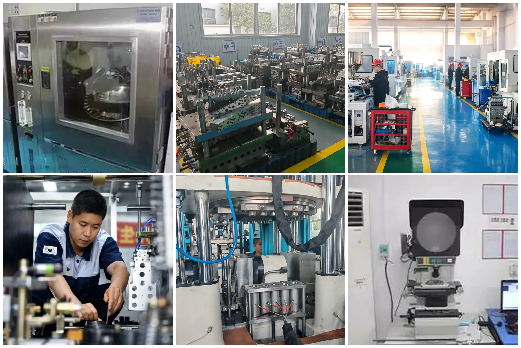
Ang Ever-Power narehistro isip Korea Ever-Power Worm And Worm Wheel Co., Ltd sa Sandan-ro, Danwon-gu, Ansan-si, Gyeonggi-do. Ang production floor naggamit ug ISO 9001:2015 quality system nga adunay IATF 16949-aligned procedures para sa automotive tier-1 programs. Kontaka ang engineering desk sa [email protected] — ang mga drowing gisusi ubos sa NDA sa dili pa mobiya sa opisina ang bisan unsang quotation.
Mga gipili nga produkto sa worm gear.
Unom ka flagship worm gear products sa ubos ang naglangkob sa pinakadaghang gipadala nga mga kategorya gikan sa linya sa Ansan — stainless para sa CNC, alloy steel para sa automotive, duplex para sa zero-backlash precision, cylindrical para sa general industrial, brass para sa micro applications, ug plastic para sa instrument drives. Ang matag card nag-link sa kompletong panid sa produkto nga adunay parameter table, mga opsyon sa materyal, ug mga detalye sa pangutana.
Mga Gamit sa Ulod nga Dili Kinamot nga Asero
DIN 5 – DIN 7 nga katukma para sa mga CNC rotary table ug machine-tool C-axis drive. 304/316 stainless para sa mga palibot nga daling madaot.
Worm ug Gear nga Asero nga Haluang
Gikarburisa ug gigaling ang SCM415 / 20CrMnTi para sa mga programa sa EPS, EPB, ug seat-actuator. Gi-align sa IATF 16949.
Duplex Worm Gear Set
Ang axial-shift worm nga adunay lainlain nga gibag-on sa ngipon makatangtang sa backlash og 30 – 40 % kon itandi sa standard catalog sets.
Ligid nga Ulod nga Silindro
Single-throat cylindrical pair, ang industrial workhorse — bronze-on-steel para sa 80 % sa general drive applications.
Ligid ug Tuhogan sa Ulod nga Tumbaga
Micro-module nga tumbaga nga ligid nga adunay gipares nga steel worm shaft para sa mga instrument drive, electronics sa opisina, ug mga medikal nga aparato.
Mga Plastik nga Worm Gear
Mga ligid nga POM ug PA66 nga grado sa inhenyeriya para sa hilom nga pagdagan ug ubos nga karga nga mga aplikasyon — kagamitan sa opisina, mga dulaan, mga gamit sa konsumidor.
Kung asa ang mga worm gears makakuha sa ilang puhunan.
Ang kasagarang aplikasyon sa mga worm gears naglangkob sa tanang suok sa industriyal nga kinabuhi — bisan asa nga ang usa ka disenyo nanginahanglan og dako nga pagkunhod sa usa ka gamay nga sobre, hilom nga operasyon, o ang abilidad sa paghawid sa karga nga walay preno. Ang upat ka panel sa industriya sa ubos naglangkob sa gibana-bana nga 70 ka % sa mga drive nga among gipadala gikan sa Ansan matag quarter. Gawas niining upat, nagpadala usab kami og regular nga mga volume ngadto sa mga kagamitan sa medical imaging, mga rig sa suga sa teatro, mga wind-turbine yaw ug pitch drive, mga solar tracker actuator, ug mga propesyonal nga broadcast pan-tilt head — tanan nga mga aplikasyon diin ang kombinasyon sa taas nga ratio, hilom nga operasyon ug kapabilidad sa self-locking dili gyud matupngan sa usa ka kakompetensya nga pamilya sa gear.
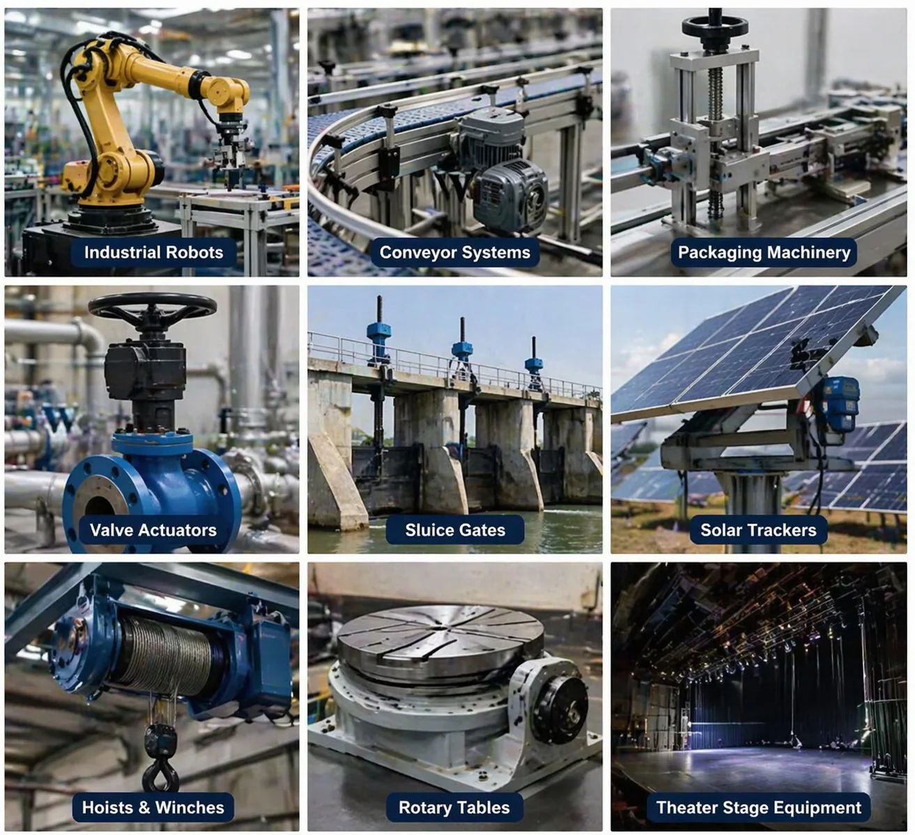
Electric power steering, seat recline motors, wiper drives, parking brake actuators — ang 20CrMnTi-on-bronze pair ang nagdominar dinhi, kasagaran DIN 6 accuracy nga adunay IATF 16949 nga dokumentasyon.
5-axis rotary tables, ATC magazines, C-axis drives sa CNC lathes — DIN 5 hangtod DIN 7 nga katukma depende sa posisyon. Ang mga ground teeth sa ligid kay standard para sa rotary-table duty.
Ang self-locking worm drives mohawid sa karga kon mawad-an og kuryente — magwagtang sa lahi nga preno nga gikinahanglan sa usa ka helical gear drive. Ang single-start worm nga adunay sub-5° lead mao ang nag-unang bahin.
Ang ubos nga rpm output ug hilom nga pagdagan naghimo sa worm gear nga standard nga kapilian para sa mga packaging lines ug food conveyors. Mas gipalabi ang stainless nga pares sa materyal para sa wash-down compatibility.
Mga bentaha, limitasyon, ug lubrication.
Ang matag pamilya sa mga gamit adunay mga kompromiso. Kini nga mga drive maayo kaayo sa pipila ka mga trabaho ug tinuod nga sayop nga pagpili sa uban. Ang matinud-anon nga balance sheet sa ubos mao ang gipasabot sa among engineering desk sa mga Korean designer atol sa unang specification call. Among girekomendar nga basahon una ang duha ka kolum sa dili pa mohimo og disenyo — katunga sa mga aplikasyon nga magsugod sa pangutana nga "kinahanglan namo og worm gear" mas maayo nga maserbisyohan sa helical o planetary stage, ug ang pag-ingon niini moresulta sa pagbaligya sa mubo nga panahon apan makatukod og matang sa pagsalig nga makamugna og lima ka balik-balik nga order sulod sa sunod nga tulo ka tuig.
Mga bentaha sa mga worm gears
- Dakong pagkunhod sa usa ka yugto. 20:1 hangtod sa 300:1 nga walay pagtapok sa mga planetary stages.
- Abilidad sa pag-lock sa kaugalingon. Mokupot sa karga nga walay lahi nga preno kon ang anggulo sa lead ubos sa mga 5°.
- 90° nga pagkahan-ay sa baras. Mousab sa direksyon ug mokunhod sa katulin sa samang component.
- Hilom ug hapsay. Ang sliding contact mopatunghag mas ubos nga kasaba kaysa bisan unsang alternatibong parallel-shaft.
- Pagsuhop sa shock. Ang sliding interface nagsilbing damper batok sa cyclic torque spikes.
- Kompakto nga sobre. Ang ratio sa densidad kada unit volume mao ang pinakataas sa bisan unsang pamilya sa gear.
Mga Limitasyon sa mga worm gears
- Mas ubos nga kahusayan. Ang sliding contact mawad-an og 10 – 50 % depende sa ratio ug lubrication — mas daghan pa kay sa spur o helical.
- Pagmugna og kainit. Ang samang pag-slide nga makahatag og hilom nga pagdagan mopatungha usab og kainit nga kinahanglan nga madala sa lana.
- Dili mabaliktad (gidisenyo). Ang self-locking usa ka feature, apan kini nagpasabot nga ang ligid dili makamaneho sa worm sa usa ka shallow-lead set.
- Sensitibo sa lubricant. Ang mga worm drive nanginahanglan og dedicated gear oils — kasagaran ang ISO VG 220 o 460 synthetic; dili paigo ang standard hydraulic oil.
- Ang pagkaguba sa ligid mao ang naglimite sa kinabuhi niini. Ang mas humok nga bronse nga ligid mas daling madaot — dahuma nga ilisan ang ligid kausa o kaduha sa tibuok kinabuhi sa worm shaft.
- Gasto sa yunit kada Nm. Alang sa parehas nga output torque, ang helical stage kasagaran 15 - 30 % nga mas barato kaysa sa worm drive.
Pag-lubricate sa worm gear sa usa ka pagtan-aw
Ang pagpili sa lubrication sa worm gear nagdepende sa sump temperature, worm rpm, ug load. Ang talaan sa ubos nagpakita sa ISO VG grade nga kasagarang girekomenda sa among engineering desk para sa matag kombinasyon — isipa kini isip sinugdanan, dili usa ka katapusang espesipikasyon. Ang mga drive nga nagdagan gawas niini nga mga kondisyon, o mga drive nga adunay dili kasagaran nga duty cycle, angayan nga susihon pag-usab ang lubrication sa dili pa ang unang pagpuno sa lana. Ang pagkuha sa husto nga viscosity grade mao ang labing epektibo nga desisyon sa service-life sa bisan unsang worm gear set — ang two-grade mismatch mahimong makapakunhod sa gilauman nga bearing ug flank life sa katunga.
| Temperatura sa sump | Ubos nga karga (≤30 % rating) | Medium nga karga | Bug-at nga karga (≥80 %) |
|---|---|---|---|
| Ubos sa 40 °C | ISO VG 150 | ISO VG 220 | ISO VG 320 |
| 40 – 70°C | ISO VG 220 | ISO VG 320 | ISO VG 460 |
| 70 – 90°C | ISO VG 320 | ISO VG 460 | ISO VG 680 synth |
| Labaw sa 90 °C | ISO VG 460 synth | ISO VG 680 synth | Pinugos nga pagpabugnaw |
Mas gipalabi ang sintetikong polyalphaolefin (PAO) o polyglycol (PAG) nga mga lana para sa temperatura sa sump nga labaw sa 70 °C — ang mga mineral nga lana dali ra kaayong mo-oxidize sa maong range. Ang mga polyglycol nga lana mohatag og gamay nga mas ubos nga friction sa sliding contact ug makapalugway sa kinabuhi sa serbisyo og 30 – 50 % sa taas nga temperatura, apan dili kini compatible sa tanang seal material — konsultaha ang among engineering desk sa dili pa i-retrofit ang PAG ngadto sa usa ka drive nga orihinal nga gitino para sa mineral nga lana.
⚠Tulo ka komon nga mga paagi sa pagkapakyas nga angay bantayan
Ang pagkahibalo kon giunsa pagkapakyas kini nga mga drive katunga na sa gubat sa pagdesinyo og usa nga molungtad. Ang tulo ka mga failure mode sa ubos naglangkob sa gibana-bana nga 85 ka % nga mga pagbalik sa warranty sa among base sa mga kustomer sa Korea — ang pag-ila niini og sayo makatabang sa maintenance team sa pagplano sa usa ka naka-iskedyul nga pag-ilis imbes nga usa ka emerhensya nga mohunong sa linya.
Gagmay nga mga lungag sa ibabaw tungod sa balik-balik nga contact stress. Gilauman nga molungtad og dugay; kon kini makita og sayo, ang drive overloaded o ang lubricant film nipis ra kaayo.
Mga marka sa longitudinal score gikan sa temporaryo nga pagkontak sa metal. Tungod sa kakulang sa lubricant, sayop nga viscosity, o kontaminasyon.
Kalit nga katalagman nga pagkapakyas. Tungod sa shock overload o kakapoy human sa dugay nga operasyon gawas sa gisukod nga service factor.
Unsaon pagpili sa hustong gamit sa ulod — sa pito ka pangutana.
Ang pito ka pangutana sa ubos naglangkob sa matag impormasyon nga gikinahanglan sa among engineering desk aron makakutlo og worm gear set o worm gearbox. Basaha kini pag-ayo sa dili pa ang unang email — ang pagbuhat niini kasagaran makapamenos sa siklo sa pagkutlo gikan sa upat ka adlaw ngadto sa ubos sa usa.


