Korea Ever-Power · Guide till applikationsteknik
Snäcka och snäckhjul för antennpositionerare och parabolantenner
A Ka-band earth station with a 1.2-metre dish has a beam width of 0.6 degrees. The satellite sits 36,000 km away in geostationary orbit. If the worm gear pair driving the antenna azimuth axis has 4 arcminutes of backlash, the pointing error consumes 11 percent of the beam width — degrading the signal by 0.5 dB and potentially dropping the link below the minimum carrier-to-noise threshold. At Ka-band frequencies, the worm gear pair backlash is a communications parameter, not just a mechanical specification.
Antenna positioners and satellite dish tracking systems use worm gear pairs for azimuth (horizontal) and elevation (vertical) axis drives because self-locking holds the antenna pointing angle against wind without motor power, the high ratio provides fine angular resolution from a compact motor, and the 90-degree geometry fits within the pedestal structure. The pointing accuracy budget table maps frequency band (C, Ku, Ka) and dish diameter to the beam width, the maximum allowable pointing error, and therefore the maximum worm gear pair backlash — revealing that C-band systems tolerate 6 to 10 arcminutes of backlash while Ka-band systems demand below 2 arcminutes. Maritime stabilised antennas add continuous tracking duty (correcting for ship roll, pitch, and yaw) that produces 5 to 15 million positioning cycles per year — a fatigue loading regime comparable to wind turbine yaw drives (Article A35) rather than the quasi-static duty of land-based fixed-point antennas.
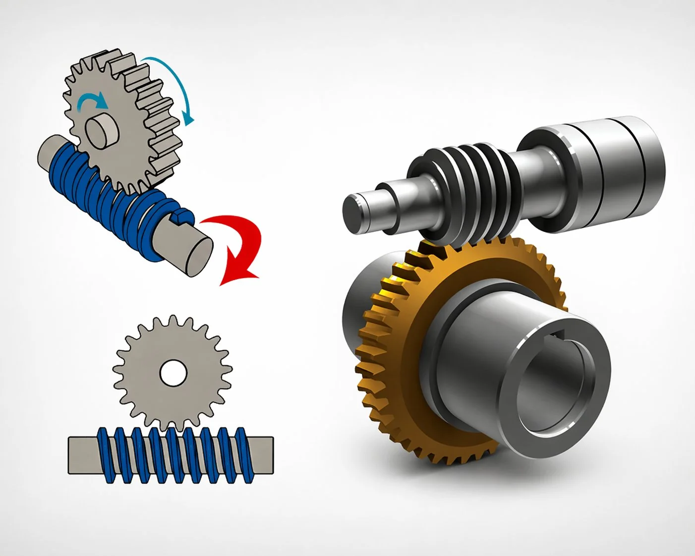
Why antenna positioners use worm gear drives
An antenna positioner rotates the dish in azimuth (0 to 360 degrees horizontal) and elevation (0 to 90 degrees vertical) to point the antenna beam at a satellite or communication target. For geostationary satellites, the antenna points once and holds — the worm gear pair is a precision positioner and a wind-resistant lock. For LEO (low earth orbit) satellites, the antenna tracks continuously as the satellite crosses the sky in 5 to 15 minutes — the worm gear pair is a precision servo actuator operating at variable speed.
Both modes demand the same three worm gear pair properties: precision angular positioning (arcsecond-level for high-frequency bands), self-locking against wind load on the dish surface, and compact pedestal integration.
A worm gear pair at 360:1 ratio with a servo encoder provides angular resolution below 1 arcsecond per encoder count — sufficient for Ka-band tracking at 40 GHz where the beam width is 0.4 to 0.8 degrees. The high ratio converts motor rotation to fine angular increments that direct-drive motors cannot match at the same cost.
A 3.7-metre dish in a 30 m/s wind generates approximately 4,000 N of thrust — producing 2,000 to 3,000 N·m of torque at the azimuth axis. Self-locking holds the dish against this load without motor power — essential for unattended remote sites where power may be intermittent.
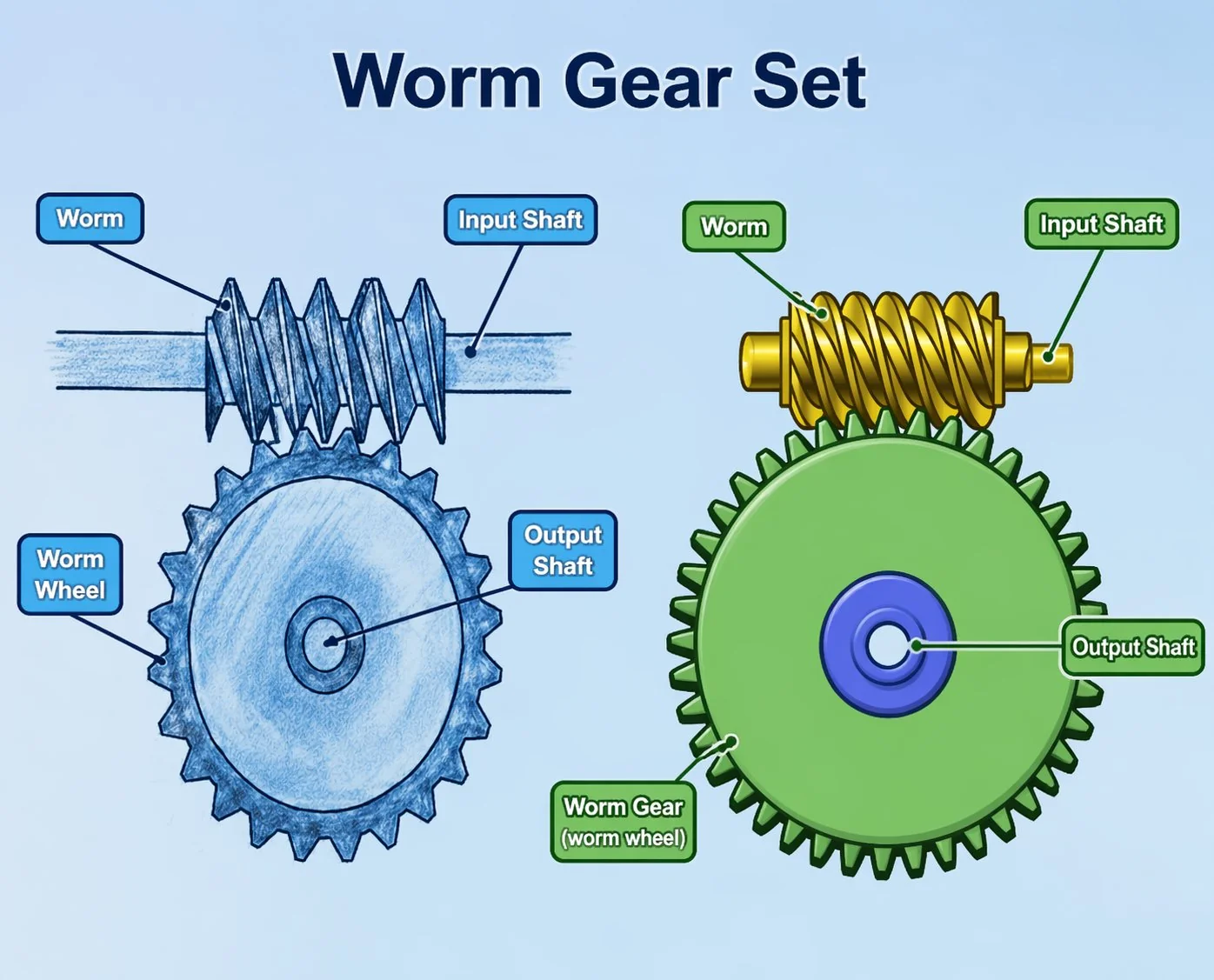
The 90-degree worm gear layout positions the motor inside the pedestal tube while the output drives the azimuth or elevation bull gear — keeping the motor out of the antenna aperture (which would block the RF signal). No other gear type achieves the perpendicular axis conversion within the pedestal envelope.
Pointing accuracy budget — frequency band and dish size to worm gear pair backlash limit
The antenna beam width determines how accurately the antenna must point — and therefore how much backlash the worm gear pair can have. Beam width is inversely proportional to both frequency and dish diameter: higher frequency and larger dish produce a narrower beam that demands tighter pointing. The pointing accuracy budget allocates a fraction (typically 10 to 20 percent) of the beam width to the worm gear pair backlash — reserving the remaining budget for structural deflection, thermal expansion, and wind-induced flexure.
The budget table reveals a 10-fold range in allowable backlash from C-band (10 arcminutes) to V-band/LEO (below 1 arcminute). A worm gear pair that is perfectly adequate for a C-band VSAT terminal becomes completely unusable for a Ka-band earth station — the same mechanical component fails the communications specification before the torque or speed are even considered. This is why antenna worm gear pair procurement must start with the RF specification (frequency band + dish size), not the mechanical specification (torque + ratio).
Maritime stabilised antenna — continuous tracking under ship motion
Land-based antennas point once and hold — the worm gear pair operates for minutes during initial alignment, then sits static for months or years. Maritime stabilised antennas are the opposite: the ship rolls (plus or minus 15 to 30 degrees), pitches (plus or minus 5 to 10 degrees), and yaws (plus or minus 3 to 5 degrees) continuously. The antenna positioner must counter-rotate on both axes to keep the beam pointed at the satellite despite the ship motion — a continuous servo loop running at 10 to 50 corrections per second.
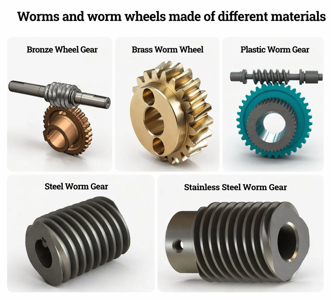
This continuous tracking produces 5 to 15 million worm gear pair positioning cycles per year — a fatigue loading regime that is 1,000 times higher than a land-based geostationary antenna and comparable to the wind turbine pitch drives discussed in Article A35. The worm gear pair material must withstand this fatigue: centrifugal-cast phosphor bronze or aluminium bronze wheels (sand-cast wheels develop fatigue cracks at the porosity sites within 2 to 3 years of maritime service). The worm must be hardened to HRC 58+ and ground to Ra 0.3 µm or better — hobbed worms produce excessive backlash growth under the continuous reversing load.
A Korean maritime VSAT manufacturer installed Ku-band stabilised antenna systems on 12 container vessels. Each antenna had two worm gear pair drives (azimuth and elevation). The original specification used standard industrial worm gear pairs — module 1.5, centre distance 35 mm, ratio 90:1, sand-cast phosphor bronze wheel, backlash 5 arcminutes. The pointing budget for Ku-band at 1.0 m dish required maximum 3 arcminutes — already marginal at 5 arcminutes initial backlash. After 18 months of continuous maritime tracking (approximately 7.5 million reversing cycles per axis), 5 of the 24 elevation-axis pairs developed backlash above 12 arcminutes — the sand-cast bronze wheels had developed subsurface fatigue cracks at casting porosity sites. Signal quality degraded on the affected vessels, producing intermittent link dropouts during heavy weather (when ship motion amplitude was highest and the worm gear pair worked hardest). Fleet-wide replacement with centrifugal-cast aluminium bronze wheels (porosity-free, superior fatigue life) and preloaded duplex specification (backlash below 2 arcminutes). Cost per replacement pair: 280 USD versus 120 USD original — a 160 USD premium. Cost of fleet-wide link quality complaints and emergency technician visits to 5 vessels across 3 continents: approximately 45,000 USD. Lesson: maritime antenna worm gear pairs must be specified for continuous-reversing fatigue, not static-load industrial duty. Centrifugal-cast (not sand-cast) wheels and preloaded (not standard-backlash) specification are mandatory for any antenna tracking a satellite from a moving platform.
Three antenna positioner worm gear pair specification cases
Case 1 — Korean maritime VSAT: Ku-band, 1.0 m dish, stabilised, continuous tracking
A Korean maritime VSAT manufacturer specified worm gear pairs for the azimuth and elevation axes of a Ku-band stabilised antenna (1.0 m dish, 14/12 GHz uplink/downlink). Beam width: 1.4 degrees. Maximum pointing error: 0.14 degrees (10 percent of beam width). Worm gear pair backlash allocation: 0.04 degrees = 2.4 arcminutes. Corrected specification (post-fleet incident): preloaded duplex, module 1.5, centre distance 35 mm, ratio 90:1, ground Ra 0.3 µm. Wheel: centrifugal-cast aluminium bronze (fatigue-rated for 20 million reversing cycles). Effective backlash: 1.8 arcminutes. Motor: 24 V DC servo with 65,536-count absolute encoder. Wind holding torque (stow position, Beaufort 10): 450 N·m. Housing: marine-grade epoxy-coated aluminium, IP66. Cost per pair: 280 USD. Two per antenna: 560 USD. Annual production: 800 antenna systems (1,600 worm gear pairs). Signal quality post-upgrade: zero link dropouts attributed to pointing error across the fleet.
Case 2 — Japanese LEO satellite tracking: Ka-band, 3.7 m dish, sub-arcsecond, ground-based
A Japanese satellite communications company specified worm gear pairs for a 3.7-metre Ka-band earth station tracking LEO satellites for broadband internet gateway service. Beam width: 0.2 degrees. Maximum pointing error: 0.02 degrees = 72 arcseconds. Worm gear pair backlash allocation: 15 arcseconds (20 percent of total pointing budget). This was below the preloaded duplex achievable limit (typically 1 to 2 arcminutes = 60 to 120 arcseconds) — requiring an additional encoder-feedback correction loop that measured actual antenna position via a precision optical encoder mounted directly on the antenna axis (bypassing the worm gear pair backlash in the control loop). Worm gear pair: preloaded duplex, module 2, centre distance 50 mm, ratio 360:1, lapped Ra 0.2 µm, DIN class 3. Effective mechanical backlash: 45 arcseconds — but the encoder feedback loop reduced the effective pointing error to below 10 arcseconds by compensating for the backlash in software. Wheel: centrifugal-cast tin bronze with nickel addition. Cost per pair: 850 USD. Two per antenna: 1,700 USD. Browse precision worm gear reducers for antenna options for satellite tracking and earth station applications.
Case 3 — Vietnamese broadcast uplink: C-band, 4.5 m dish, fixed geostationary, cost-optimised
A Vietnamese television broadcaster specified worm gear pairs for the azimuth and elevation drives of a 4.5-metre C-band uplink antenna pointing at a geostationary satellite. Beam width: 0.8 degrees. Maximum pointing error: 0.08 degrees = 4.8 arcminutes. The generous C-band budget allowed a standard (non-preloaded) worm gear pair at 6 arcminutes backlash — well within the 4.8 arcminute allocation with margin. The antenna pointed once at installation and was readjusted only during annual maintenance — essentially zero operational cycles per year (the ultimate low-duty application). Worm gear pair: single-start, module 3, centre distance 80 mm, ratio 72:1, ground Ra 0.4 µm. Standard phosphor bronze wheel (no fatigue requirement — zero cycling). Wind holding torque at the 4.5 m dish: 3,200 N·m (design wind 35 m/s). Housing: hot-dip galvanised, IP55. Cost per pair: 145 USD. Two per antenna: 290 USD. The specification demonstrates that C-band fixed-point antennas are among the least demanding worm gear pair applications in any industry — lower precision, lower duty, and lower cost than a packaging machine indexing drive (Article A16).
Vanliga frågor
Q: How do I calculate the worm gear pair backlash budget for my antenna?
Start with the 3 dB beam width: BW = 70 × λ / D (degrees), where λ is wavelength (m) and D is dish diameter (m). The maximum allowable total pointing error is typically 10 to 20 percent of the beam width (depending on the link budget margin). Allocate 20 to 30 percent of the total pointing budget to worm gear pair backlash (reserving 70 to 80 percent for structural deflection, thermal expansion, and wind flexure). Example: Ka-band at 30 GHz (λ = 0.01 m), D = 2.4 m: BW = 70 × 0.01 / 2.4 = 0.29 degrees. Total error budget at 15 percent: 0.044 degrees = 2.6 arcminutes. Worm gear pair allocation at 25 percent: 0.65 arcminutes = 39 arcseconds. This requires a preloaded duplex pair — standard pairs cannot achieve below 1 arcminute.
Q: Why does maritime antenna tracking wear out worm gear pairs faster than land-based?
A land-based geostationary antenna adjusts position once (during installation) and holds — the worm gear pair may execute fewer than 100 positioning cycles per year. A maritime stabilised antenna continuously corrects for ship roll, pitch, and yaw — executing 10 to 50 corrections per second, 24 hours per day, producing 5 to 15 million reversing cycles per year. This continuous reversing load produces contact fatigue on the wheel tooth flanks that standard industrial worm gear pairs are not designed for. Sand-cast bronze wheels (which contain micro-porosity from the casting process) develop subsurface fatigue cracks at these porosity sites within 2 to 3 years. Centrifugal-cast or forged wheels (porosity-free) last 8 to 12 years under the same maritime tracking duty.
Q: Can encoder feedback compensate for worm gear pair backlash in antenna tracking?
Yes — by mounting a precision encoder directly on the antenna axis (after the worm gear pair) rather than on the motor shaft (before the pair). The axis-mounted encoder measures the actual antenna angle including backlash, and the servo controller compensates by adjusting motor position. This technique can reduce the effective pointing error to 10 to 20 percent of the mechanical backlash — enabling a pair with 3 arcminutes of mechanical backlash to achieve sub-arcminute effective pointing. The trade-off: axis-mounted encoders cost 800 to 3,000 USD (versus 50 to 200 USD for motor-shaft encoders) and require precision mounting that adds assembly complexity. This approach is standard for Ka-band and LEO tracking systems where the pointing requirement exceeds the mechanical backlash achievable by any worm gear pair.
Q: What corrosion protection do outdoor antenna worm gear pairs need?
Most land-based antennas operate in standard outdoor environments (ISO 12944 C2 to C3) where hot-dip galvanised housing and standard seals provide 15+ years of service. Maritime antennas operate at C5-M (the same marine classification as winch drives in Article A29) requiring 316L stainless or marine-coated housing with FKM seals. Coastal land-based antennas within 1 km of the sea may experience C4 conditions requiring epoxy-coated housing and EPDM seals. The corrosion specification is independent of the pointing accuracy specification — a C-band antenna with relaxed backlash still needs C5-M corrosion protection if mounted on a ship.
Q: What is the typical service life of an antenna positioner worm gear pair?
Land-based geostationary: 15 to 25 years (essentially zero cycling — corrosion and seal degradation are the life-limiting factors). Land-based LEO tracking: 8 to 15 years (moderate cycling at 500 to 2,000 tracks per day). Maritime stabilised: 5 to 10 years (continuous high-cycle fatigue — centrifugal-cast wheels extend to 8 to 12 years). The worm itself lasts the life of the antenna in all cases (hardened steel, ground finish, low contact stress). The wheel is the consumable element — plan replacement at the same interval as the antenna feed electronics refurbishment.
Antenna positioner worm gear pairs bridge the gap between mechanical engineering and RF communications — the backlash in the gear pair directly determines the antenna pointing accuracy, which determines the signal quality at the satellite link. The pointing accuracy budget table maps frequency band and dish diameter to the maximum allowable backlash — revealing that Ka-band and LEO tracking demand preloaded duplex pairs with sub-arcminute backlash, while C-band fixed-point systems tolerate standard industrial pairs at 6 to 10 arcminutes. Maritime stabilised antennas add continuous-reversing fatigue at 5 to 15 million cycles per year — requiring centrifugal-cast wheels and preloaded specification that sand-cast standard pairs cannot survive. For antenna manufacturers, the worm gear pair specification starts with the RF link budget, not the mechanical torque calculation.
For antenna manufacturers and satellite communications companies, our engineering desk calculates the pointing budget from your RF specification and recommends the worm gear pair backlash class. Standard catalogue precision worm gear sets cover antenna positioner sizes from 25 to 100 mm centre distance with standard and preloaded duplex options. Submit an antenna drive specification with frequency band, dish diameter, tracking type (fixed/LEO/maritime), and wind design speed.
Specifying worm gear pairs for antenna positioners?
Send frequency band, dish diameter, tracking type (geostationary, LEO, maritime), wind design speed, and whether the antenna is land-based or vessel-mounted. We will calculate the pointing budget and recommend the backlash class, preload method, and corrosion specification.
Redaktör: Cxm


