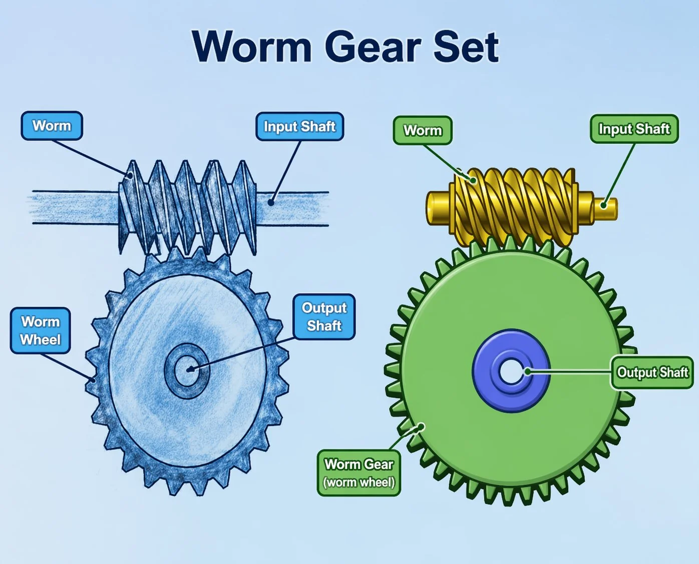
Како одабрати пужни зупчаник — инжењерска контролна листа од 7 питања
Walk seven questions in order and the spec writes itself. Skip a step and you ship a drive that fails warranty in eight months.
Worm gear selection is not a parameter calculator — it is a sequence of seven engineering decisions, each of which eliminates options for the next. Define output torque and rpm first, decide the ratio, settle the self-locking question, choose the throat geometry, pick the material pair, fix the mounting and accuracy class, then decide between buying a bare set, a complete reducer, or a packaged motor-gearbox unit. The first three questions decide 80 percent of the outcome. Skipping any of them is the single most common reason new specifications fail in the field.
Why a sequence beats a checklist — and Question 1: torque and rpm
Open any worm gear selection guide and you will see the same list of considerations: torque, speed, ratio, efficiency, material, lubrication, mounting, environment, accuracy, cost. The list is correct but useless — it tells you what to think about without telling you what to think about first. A new specifier reading that list is presented with ten variables and no order, gets overwhelmed, and either copies a previous specification verbatim or leaves the gearbox details to a salesperson who has incentives the engineer does not share.
The seven questions below are sequenced by how much they constrain the rest of the choice. Question 1 has to be answered first because nothing else can be decided without its answer. Question 2 has to be answered second because it depends on Question 1. By the time you reach Question 7, the answer space is small enough that the decision falls out almost automatically. Walk the questions in order, write down each answer, and the specification is essentially complete by the end of the seventh.
Two numbers must be on the table before any other decision: output torque (in N·m) and output rpm. Everything else flows from these. Calculate the output torque for the worst case in your duty cycle, not for the average case — the gear set sees the peak load, not the mean. Apply a service factor of 1.3 for light intermittent duty, 1.5 for general industrial duty, 2.0 for shock-loaded or 24-hour continuous duty, and 2.5 for hoist or crane duty.
Output rpm is whatever the driven equipment needs at its operating point. If you are driving a conveyor at 0.5 m/s with a 200 mm pulley, output rpm is 47.7. If you are indexing a rotary table 90 degrees in 1.2 seconds, peak output rpm is roughly 12.5. If the driven equipment changes speed during the duty cycle (most servos do), use the peak speed for sizing — heat dissipation is dominated by peak operation, not by mean.
Almost every selection mistake we see in the field traces back to wrong numbers at this step. A designer takes a steady-state torque calculation as the design value when the application has shock loads twice as large. A controller integrator forgets that motor inrush adds 50 percent to the calculated steady torque during the first second of every start cycle.
Be honest with yourself about peak conditions before you ask the next question. Round up rather than down on the torque number. The unit cost penalty for one frame size larger is small; the cost of a warranty failure six months in is enormous.
Question 2 — What reduction ratio falls out of those numbers?
Decide the input speed first — usually a standard 3-phase motor at 1,400 rpm (50 Hz, 4-pole) or 1,750 rpm (60 Hz, 4-pole), or a servo at whatever continuous speed the application needs. Required ratio = input rpm divided by output rpm. Round to the nearest practical integer-tooth ratio.
If the math gives 35:1, your candidate ratios are 35:1 (Z₁=1, Z₂=35), 30:1 (Z₁=2, Z₂=60), or 36:1 (Z₁=1, Z₂=36) — pick whichever matches your other constraints. If the math demands more than 100:1, you are pushing the practical single-stage limit; consider a two-stage drive (worm + spur, or worm + planetary). If the math gives less than 5:1, a worm gear is probably the wrong technology — look at helical or planetary first.
The sweet spot for worm and worm wheel pairs is 10:1 to 80:1 single stage. Above 80:1, efficiency drops below 50 percent and heat becomes a binding constraint. Below 10:1, you are paying for the worm geometry without using its core advantage. Ratios outside the sweet spot are technically possible but rarely the cheapest answer per kW of power transmitted.
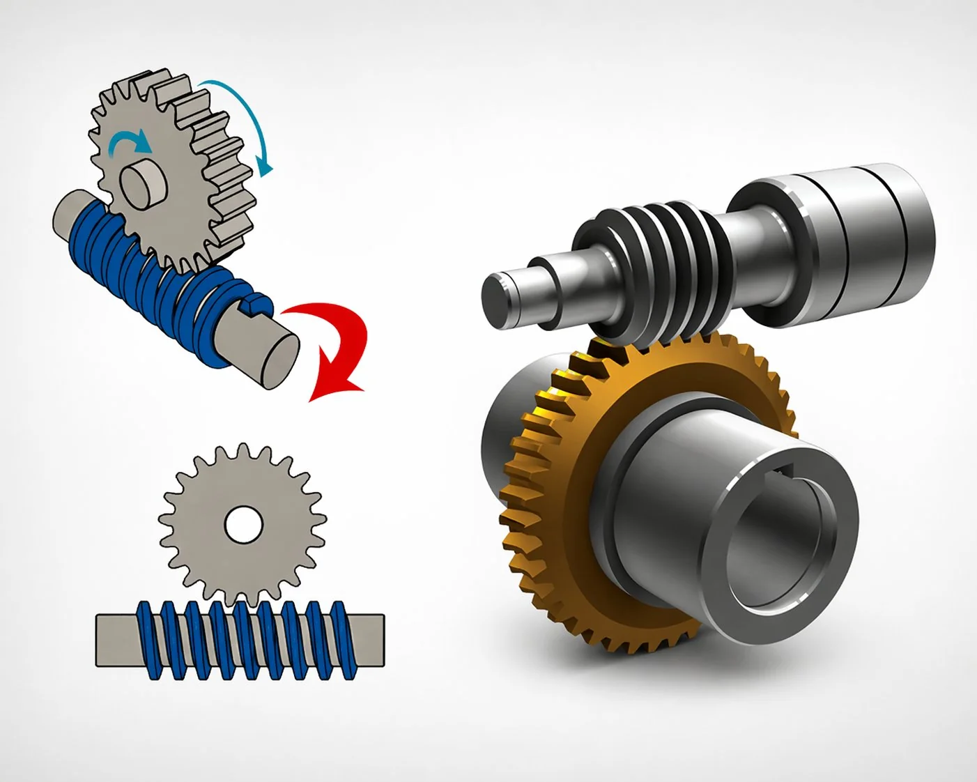
Question 3 — Do you need self-locking?
This question has only three valid answers: yes, no, and “the application would benefit but I have a separate brake anyway.” The decision changes everything downstream.
Yes (mandatory) means the lead angle has to be below 5 to 6 degrees, which forces a 1-start worm with a small pitch diameter, which forces a higher ratio, which forces lower efficiency (typically 40 to 65 percent). Hoists, valve actuators, gate openers, manual override mechanisms, antenna positioners, and any application where back-drive would be dangerous fall in this category.
Important: never rely on self-locking as the sole safety device for a falling-load application — fit a separate mechanical brake and treat self-locking as a useful auxiliary.
No (back-drive acceptable or desirable) means you can use a multi-start worm with higher lead angle, accept higher efficiency (75 to 92 percent), and the drive will free-wheel when the motor stops. Conveyors, mixers, fans, ventilation drives, and most general industrial duty fall here. The efficiency saving over the life of the drive often pays the small extra cost of a brake on the motor for the rare case when controlled stopping is needed.
Don’t care means you have a separate brake or the load naturally decays — choose lead angle for efficiency, not for self-locking, and pick whatever ratio meets Question 2.
In two decades of reviewing first specifications from new OEM customers, the most expensive mistake I have seen is overspecifying self-locking when the application does not need it. A multi-start worm at 88 percent efficiency draws roughly half the motor power of a self-locking single-start worm at 60 percent efficiency for the same output torque. Over a 24-hour-per-day production cycle, that gap pays for the entire gearbox in two years through electricity savings alone. Ask Question 3 honestly before being seduced by the safety appeal of self-locking.
Question 4 — Throat geometry: non-throat, single, or double?
Throat type changes the contact area between worm and wheel and therefore changes load capacity by factors of two and three. The decision matrix is simple once you have the answers to Questions 1 through 3.
Single-throat is the default and the right answer for roughly four out of five worm and worm wheel orders. Pay the 50 percent cost premium for double-throat only when the duty cycle, output torque, or shock loading actually demands it. Pay the lower cost of non-throat only when service life requirements are modest and the unit cost difference matters more than longevity.
Question 5 — What material pair fits the operating environment?
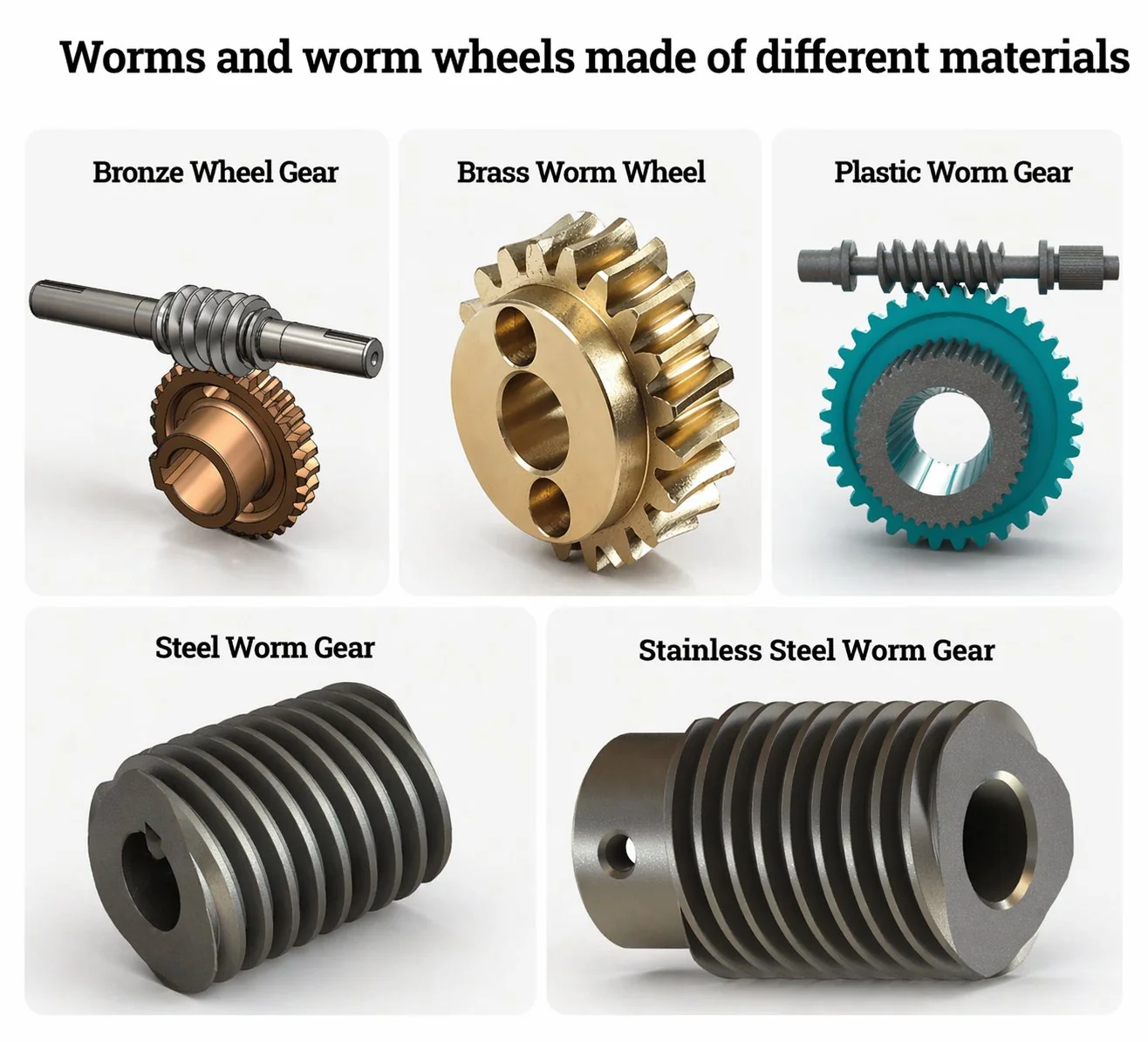
Material selection is governed by the 2:1 hardness rule — the worm shaft must be roughly twice as hard as the worm wheel. Within that rule, the right pair depends almost entirely on operating environment, not on what the parts will be doing.
If you are unsure between two pairs, default to phosphor bronze. It covers roughly 70 percent of orders and is the safe choice when the application does not actively demand a different pair.
Question 6 — How will it mount and what accuracy class is needed?
Mounting determines how the bare gear set integrates with the rest of your machinery. The wheel can be supplied with a keyway, with set-screw mounting, with a split hub for high-torque applications, with a flange face for direct bolting, or with an integral shaft. Each option trades assembly time, maintenance accessibility, and torque transmission capacity differently.
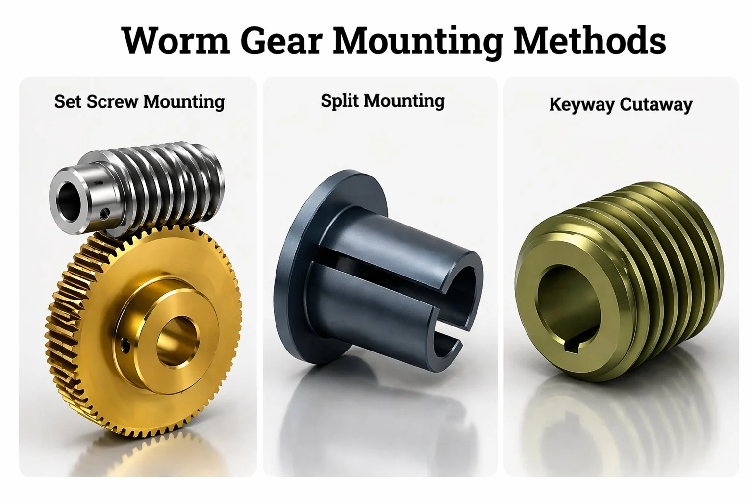
Keyway mounting is the industrial default — easy to install, easy to replace, transmits high torque through the positive mechanical lock. Set-screw mounting is faster on assembly but limited to lower torques and prone to slip under shock load. Split-hub mounting is the choice for very high torque applications where keyway shear is a concern.
Accuracy class (DIN 5 / 6 / 7 / 8) drives 15 to 25 percent of unit cost. DIN 8 hobbed-only wheels are fine for general drives. DIN 7 is standard industrial accuracy. DIN 6 needs shaving after hobbing — common in machine tool indexing. DIN 5 needs grinding — used only when positioning accuracy under one arc-minute is required.
Question 7 — Bare set, complete reducer, or motor-gearbox unit?
Three procurement formats serve different production realities. The choice has cost and integration consequences worth thinking about before placing the order.
Bare worm and worm wheel set — just the two precision components, no housing, no bearings, no seals. Cheapest unit cost, maximum design flexibility, but you are taking responsibility for housing design, bearing selection, oil seal arrangement, and lubrication system. This format suits OEMs with their own machined housings (machine-tool builders, custom indexing tables, specialty rotary actuators).
Complete worm gear reducer (gearbox) — sealed cast-iron or aluminium housing with the worm and wheel pre-assembled, lubricated, and tested. The output flange or shaft mates directly to your driven equipment. The input shaft mates to your motor through a coupling. Use this format when you do not want to design the housing yourself and you have an existing motor to drive it. Most general industrial conveyor and packaging line drives sit in this category. Browse complete пужни редуктор options to compare typical frame sizes, shaft layouts, and standard ratios.
Motor-gearbox combined unit (gearmotor) — reducer with the electric motor pre-mounted and pre-aligned. Single SKU, single nameplate, single warranty. Highest unit cost but lowest installation time. Choose this format when production cycle time matters more than per-unit cost, when you are buying small quantities, or when you do not have a coupling and motor mounting infrastructure. Common in OEM equipment with one drive per machine and high build volume.
Three real selection scenarios — the questions in action
Scenario 1 — Korean automotive seat-track actuator
Tier-1 supplier needs a compact drive for an electric seat-track actuator. Output torque 8 N·m, output speed 30 rpm, must hold position when motor stops, vehicle interior environment, annual volume 800,000 units. Walking the seven questions: (1) 8 N·m × 1.5 service factor = 12 N·m, 30 rpm. (2) 12V DC motor at 4,000 rpm, ratio 4,000 / 30 ≈ 130:1. (3) Self-locking mandatory because seat must hold occupant weight without back-drive when motor stops. (4) Single-throat — light load, high volume, cost-driven. (5) Plastic worm + plastic wheel — load is below threshold, silent operation matters in passenger cabin. (6) Integral shaft with snap-fit retainer for high-volume assembly. (7) Complete gearmotor unit with brushed DC motor pre-mounted. Final spec settles in 30 minutes once Question 1 is honest about peak load.
Scenario 2 — Japanese pharmaceutical mixer drive
Pharmaceutical equipment OEM needs a sterile-compatible mixer drive. Output torque 180 N·m, output speed 80 rpm, FDA and EHEDG compliant, 16-hour daily duty, must withstand steam clean-in-place at 134°C. Walking the questions: (1) 180 × 1.5 = 270 N·m, 80 rpm. (2) 1,400 rpm motor / 80 rpm = 17.5 → round to 18:1 with Z₁=2, Z₂=36 (multi-start for efficiency). (3) Self-locking not needed — mixer freewheels harmlessly. (4) Single-throat — torque well within capacity. (5) 17-4PH stainless worm + 316 stainless wheel — regulatory non-negotiable. (6) Flange-mount complete reducer for steam wash-down compliance. (7) Complete gearbox without integral motor — customer prefers their own washdown-rated motor. Final spec satisfies regulatory and mechanical constraints in one pass.
Scenario 3 — Vietnamese cement plant slurry conveyor
Cement producer needs replacement drives for slurry conveyors at a quarry. Output torque 850 N·m, output speed 25 rpm, dusty environment, occasional shock loads from material clumps, 24-hour continuous operation, capital cost is the dominant procurement constraint. Walking the questions: (1) 850 × 2.0 (continuous + shock factor) = 1,700 N·m, 25 rpm. (2) 1,400 / 25 = 56:1 → round to 60:1, Z₁=1, Z₂=60. (3) Self-locking neutral — belt naturally decays under friction. (4) Double-throat — high torque, continuous duty, shock loads, the cost premium pays back through service life. (5) SCM415 worm + CuAl10Fe5Ni5 aluminium bronze wheel — dusty environment plus continuous heavy duty rules out phosphor bronze. (6) Foot-mount cast-iron housing with overhung load capacity for sprocket drive. (7) Complete reducer without motor — customer reuses existing 7.5 kW motor stock. Capital cost lands 35 percent higher than the existing single-throat phosphor-bronze design but service interval extends from 14 months to roughly 4 years, paying back in less than half that time.
What to send when you ask for a quotation
Once you have walked the seven questions, package the answers in a request for quotation. The information our engineering desk needs to produce a meaningful quote (and the same applies to any reputable supplier) is shorter than first-time specifiers expect:
- Output torque (N·m) including service factor — the calculated worst-case number, not the average.
- Output rpm at the operating point — peak rpm if the speed varies during the duty cycle.
- Input rpm and motor type (3-phase induction, servo, DC, hand-crank).
- Self-locking required, optional, or undesirable — be specific.
- Operating environment — temperature range, humidity, chemical exposure, food contact, dust, vibration.
- Duty cycle — hours per day, percent on / off, expected service life in hours or years.
- Mounting interface — keyway, set screw, flange dimensions, integral shaft, hub bore.
- Accuracy class if it matters (most general drives do not need to specify this — accept supplier default).
- Whether you want a bare set, complete reducer, or gearmotor.
- Any external constraints — packaging envelope, weight limit, NDA requirements, country of origin certification.
Sending this package — typically a one-page form plus an envelope drawing — usually returns a meaningful quote within one to two working days. Vague requests like “I need a worm gear for my machine” return generic catalogue listings that may or may not match your application.
Често постављана питања
Q: What service factor should I use for a conveyor drive?
For light-duty conveyors transporting product at constant speed (8 to 12 hours per day, smooth load), 1.3 is reasonable. For heavier industrial conveyors with shock loads from product entering or exiting (16 hours per day, occasional jam events), 1.5 to 1.7. For 24-hour quarry, mining, or aggregate conveyors, 2.0. The service factor multiplies your calculated steady-state torque to account for real-world variation. Apply it before sizing the gearbox, not after.
Q: How do I know if my application needs a multi-stage drive?
If the calculated single-stage ratio exceeds 80:1 and efficiency drops below 50 percent, consider a two-stage approach. Below 100:1 most applications can stay single-stage. Above 150:1 a two-stage drive (worm + spur, or worm + planetary) is usually cheaper to operate over the lifetime because the second stage runs at high efficiency, more than compensating for the extra component cost. Above 250:1, single-stage worm is rarely the right answer — the heat budget and cost equation both favour staged reduction.
Q: My drive runs intermittently — how does that change the selection?
Intermittent duty (less than 50 percent on-time) lets you reduce the service factor toward the lower end of the range, and lets the housing dissipate heat between cycles. Intermittent applications often allow non-throat or smaller single-throat geometry that would not survive continuous duty. State the duty cycle explicitly in the quotation request — “60 percent on, 40 percent off, two-minute cycle” is far more useful than “intermittent.”
Q: Is it cheaper to buy a complete reducer or assemble a bare set into my own housing?
Almost always cheaper to buy a complete reducer for low-to-medium volumes. The cost of casting your own housing, sourcing precision bearings, fitting oil seals, and pressure-testing a custom drive runs to several thousand USD per unit even before you factor in development time. Bare sets make sense only for very high-volume OEM products where the housing is amortised across thousands of pieces, or for very specialised applications where no catalogue housing fits. For most OEM customers shipping under 5,000 pieces per year, complete reducer is the right answer.
Q: How do I size for a vertical-mount drive?
Vertical mounting affects oil retention, not torque calculation. The torque math is identical to a horizontal drive — what changes is the housing seal arrangement and the oil fill level. Specify “vertical input” or “vertical output” explicitly in the quotation, because most catalogue gearboxes default to horizontal and vertical orientations need a different oil-fill level, sometimes a different shaft seal, and occasionally a different oil grade. The supplier will usually have a vertical-rated variant of the same gearbox at a small price premium.
Q: What documentation should the supplier provide with the gearbox?
For ordinary commercial-grade orders: dimensional drawing, ratio confirmation, oil specification, and a basic warranty document. For OEM-grade orders: material certificates for both worm and wheel, hardness reports, geometric inspection record (concentricity, pitch error, contact pattern), oil-fill record, and a serial number traceable to the production batch. For regulated applications (food, pharma, marine certified): all of the above plus FDA / EHEDG / DNV / ABS compliance documentation as relevant. Specify the documentation needed in the request for quotation — most suppliers will provide it but only if asked.
Q: How long should the design and quotation cycle take?
A complete request for quotation with all seven questions answered should return a quote in one to two Korean working days from a competent supplier. If the supplier asks for technical clarification before quoting, that is normal and usually a sign they are paying attention. Quotations that arrive within an hour without any clarifying questions are usually generic price lists rather than application-matched recommendations. Treat them with appropriate scepticism.
Worm gear selection is not difficult once the seven questions are answered in order. Most failures come from skipping Question 1 (sloppy torque numbers), Question 3 (overspecifying self-locking), or Question 5 (wrong material pair for the environment). Walk the questions, write down the answers, and the rest of the specification is essentially derivable. Skipping any question almost always returns a drive that does not match the application.
For Korean and Japanese OEM design teams that want a specification reviewed before tooling commitment, our engineering desk runs a full seven-question audit and quotes against the matching пужни зупчаници од бронзе и легираног челика in our standard catalogue. Custom geometries outside the catalogue are made to order against drawing — request a worm gear specification audit and our team will return a recommendation, ratio, material pair, and price tier within one Korean working day.
Have the seven answers? Send them through.
Output torque, output rpm, input rpm, self-locking yes/no, environment, duty cycle, mounting preference. With those seven items in hand, our engineering desk turns around a fully specified quote in one to two working days.
Уредник: Cxm


