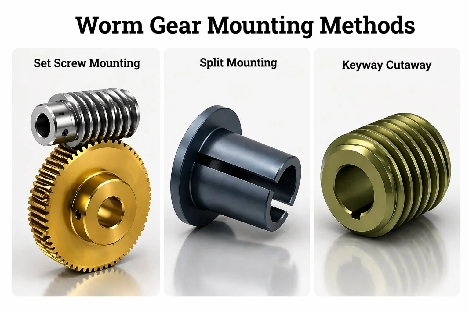
Wormwielmontage — Vergelijking van spiebaan, stelschroef en gesplitste naaf
Drie manieren om een wormwiel aan een as te bevestigen. Kies je de verkeerde, dan verandert een storing op dinsdag in een reparatie op donderdag. Kies je de juiste, dan is het onderhoudsteam je jarenlang dankbaar.
Montage met spiebanen is de industriële standaard: hoge koppeloverdracht via een positieve mechanische vergrendeling, die in 30 minuten door elke onderhoudstechnicus met een trekker en een hamer kan worden vervangen. Montage met stelschroeven is het snelst te installeren (5 minuten), maar beperkt tot lichte tot middelzware toepassingen en gevoelig voor slippen bij schokbelastingen. Klemmen met een gesplitste naaf kan de hoogste koppels aan en is beter bestand tegen losraken door trillingen dan de andere twee methoden, maar de installatie vereist een specifieke aanhaalvolgorde en de onderdelen kosten ongeveer 40 procent meer. Stem de methode af op de gebruikscyclus, niet op wat de assemblagemedewerker het gemakkelijkst vindt. Een verkeerde keuze kan een spiebaanvervanging van 30 minuten veranderen in een asvervanging van een halve dag.
Waarom de montagemethode net zo belangrijk is als de tandwielgeometrie
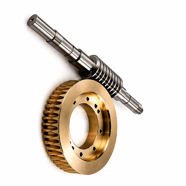
Een wormwiel moet aan een wormwielas vastzitten. Die zin klinkt onbelangrijk, totdat je op een maandagochtend om 8 uur in een onderhoudshal staat, terwijl een cementfabriek op halve capaciteit draait, omdat het wormwiel in het weekend van zijn as is gegleden, een vlak stuk tegen de spiebaan heeft gesleten en nu zowel het wiel als de as niet meer te gebruiken zijn. De montagemethode bepaalt of dit scenario theoretisch blijft of de reden wordt voor een slechte week voor de onderhoudsmanager.
Drie methoden dekken ongeveer 95 procent van de industriële wormwiel- en wormwielinstallaties: spiebaan, stelschroef en gesplitste naaf. Elk van deze methoden brengt koppel over via een ander fysiek mechanisme, neemt een andere installatie- en vervangingstijd in beslag en is in verschillende mate bestand tegen misbruik. De keuze lijkt technisch vanuit het perspectief van de ontwerper en praktisch vanuit de werkplaats – beide perspectieven zijn belangrijk en lopen vaak uiteen.
Hoe elke methode daadwerkelijk koppel overbrengt
Inzicht in het koppeloverdrachtsmechanisme vormt de basis voor elke andere beslissing. Elke methode verwerkt de belasting via een ander fysiek pad, wat de wijze van falen bij overbelasting bepaalt.
De belasting van de spiebaan ontstaat door afschuiving als gevolg van een parallelle spie. De belasting van de stelschroef ontstaat door een klein puntcontact waar de schroef in de as graaft. De belasting van de splitnaaf ontstaat door wrijvingskrachten over het gehele contactvlak tussen boring en as. Drie verschillende mechanismen, drie verschillende draagvermogens, drie verschillende faalpatronen.
Spiebaan — koppel door een stalen spie in afschuiving
Er wordt een rechthoekige gleuf gefreesd over de lengte van de as en een overeenkomende gleuf door de boring van de wormwielnaaf. Een parallelle spie (rechthoekige doorsnede, gehard middelmatig koolstofstaal, JIS- of DIN-norm) wordt in de gleuf van de as geplaatst. Het wiel schuift erop, de gleuven lijnen zich uit en de spie overbrugt de twee – half ingebed in de as, half ingebed in de naaf. Wanneer de wormas het wiel aandrijft, wordt koppel overgebracht van de as naar de spie door schuifspanning op de zijvlakken van de spie, en vervolgens van de spie naar de wielnaaf door hetzelfde mechanisme op de tegenoverliggende zijvlakken.
De oorzaak van het falen is spiebreuk. De spie is opzettelijk het zwakste element in het krachtpad – zo gedimensioneerd dat deze bij extreme overbelasting vervormt of afbreekt voordat de veel duurdere wormwielas en het wormwiel beschadigd raken. Meestal is er een stelschroef bovenop de spie (of loodrecht op de spiebaan) gemonteerd om axiale verschuiving te voorkomen; de stelschroef brengt geen koppel over, maar houdt de spie alleen op zijn plaats.
Stelschroef — koppel via een puntcontact
Er wordt een klein schroefdraadgat radiaal door de wormwielnaaf geboord, waarna een stelschroef met geharde punt erin wordt geschroefd totdat de punt in het asoppervlak graaft. Het koppel wordt van de as naar het wiel overgebracht door de wrijving van dat ene contactpunt (of twee contactpunten, als er een tweede stelschroef onder een hoek van 90 graden wordt gemonteerd). Het mechanisme is in feite een gecontroleerde kras onder hoge druk: de geharde punt van de schroef in de wormwielnaaf vervormt plastisch een klein deukje in het asoppervlak, waardoor de rotatie mechanisch wordt tegengehouden.
Het defect treedt op door slippen van de stelschroef: de uitsparing slijt, trillingen zorgen ervoor dat de schroef loskomt en het wormwiel begint te draaien ten opzichte van de wormas. Zodra de slip op de naaf van het wormwiel begint, neemt de wrijving op het oorspronkelijke contactpunt af, draait het wiel sneller en binnen enkele uren is het oppervlak van de wormas over de gehele omtrek, ter hoogte van de uitsparing, beschadigd. De as is meestal afgeschreven; het wiel kan, afhankelijk van de slijtage van de boring, mogelijk nog hergebruikt worden.
Gesplitste naaf — koppel door middel van klemmingswrijving
De wormwielnaaf is voorzien van een of twee langsgroeven in de wand, plus radiale boutgaten die de randen van de groeven naar elkaar toe trekken wanneer de bouten worden aangedraaid. De boring is zo gedimensioneerd dat het wiel er soepel op de as valt. Door de klembouten van het wormwiel aan te draaien, vervormt de naaf elastisch naar binnen, waardoor een gelijkmatige wrijvingsdruk ontstaat over het gehele contactoppervlak tussen boring en as. Het koppel wordt van de as naar het wiel overgebracht door pure wrijving over een groot contactoppervlak, zonder schuifkracht en zonder puntcontact.
Het probleem ontstaat door het losraken van de klem als het aanhaalmoment van de bouten niet correct is, maar correct aangedraaide split-hub-koppelingen gaan zelden kapot. Verwijderen is eenvoudig: draai de klembouten los en het wiel schuift er zonder weerstand af, waardoor zowel de as als het wiel onbeschadigd blijven. De kosten zitten hem in het wormwiel zelf: split-hub-ontwerpen vereisen extra bewerkingen (sleuven, boutgaten, fijnere oppervlakteafwerking van de boring) en verhogen de kostprijs per eenheid met ongeveer 40 procent in vergelijking met een equivalent met spiebaan.
Vergelijking op de vier belangrijke dimensies
Elke selectiegids voor montagemethoden beoordeelt de drie opties op koppelcapaciteit. Die ene dimensie is echter te beperkt. Het onderhoudsteam hecht evenveel waarde aan de installatietijd, vervangingstijd en trillingsbestendigheid van wormwieloverbrengingen als de ontwerper aan het maximale koppel. Hieronder vindt u de vierdimensionale beoordelingsmatrix die we aan OEM-klanten geven wanneer ze vragen welke montagemethode ze moeten specificeren.
De vermelding "goed als de spie vastzit" verbergt een belangrijk detail. Een parallelle spie in een open spiebaan zonder borging zal bij aanhoudende trillingen losraken. Specificeer altijd een borgmethode: een stelschroef die op de spie drukt, een drukring of een gesloten spiebaan. Zonder borging daalt de trillingsbestendigheid van de spiebaan naar "slecht".
Montageprocedure voor elke methode

Spiebaan (met krimpnaaf)
- Controleer of de afmetingen van de spiebaan van de as en de naaf overeenkomen met de JIS B1301- of DIN 6885-norm voor de asdiameter — doorgaans een vierkante spie voor assen tot 22 mm, een rechthoekige spie daarboven. Ontbraam beide spiebaanranden.
- Controleer de oppervlakteafwerking van de as bij de wiellagering — Ra lager dan 1,6 µm. Polijst met een schuurdoek als het oppervlak ruw of geoxideerd is.
- Plaats de parallelle spie in de spiebaan van de as. De spie moet er stevig in passen zonder vast te lopen en moet iets onder het bovenvlak van de as zitten, zodat deze de toegang tot de naafboring niet belemmert.
- Verwarm de wielnaaf tot ongeveer 120 graden Celsius in een inductieverwarmer of oliebad. De boring zet voldoende uit om over de spie op de as te schuiven.
- Schuif de naaf binnen 30 tot 60 seconden op de as – werk snel voordat de naaf afkoelt en vastloopt. Controleer of de spiebaan in de naaf goed uitgelijnd is met de sleutel tijdens het indraaien.
- Laat het geheel afkoelen tot omgevingstemperatuur. De krimpverbinding klemt de as volledig vast, waarbij de spie het koppel overbrengt en rotatie tijdens de afkoelfase voorkomt.
- Plaats de stelschroef voor de sleutelborging – meestal onder een hoek van 90 graden ten opzichte van de sleutelbaan, of direct boven het sleutellager op het bovenvlak. Breng een middelsterke schroefdraadborging aan.
Stelschroef (enkel- of dubbelpunts)
- Controleer of de wielboring een slippassing heeft op de as — er mag een kleine speling zijn, geen belemmering. Ontbraam zowel de boring als de as.
- Voor montage met twee bevestigingspunten is de wielnaaf voorgeboord met twee radiale schroefgaten onder een hoek van 90 graden. Controleer of de schroefdraad schoon is.
- Schuif het wormwiel op de as. Plaats het wormwiel tegen een willekeurig bevestigingspunt (schouder, borgring) op de as.
- Draai de eerste stelschroef vast met het door de fabrikant aangegeven koppel — doorgaans 6 N·m voor M6-schroeven met conische kop op schachtdiameters tot 25 mm.
- Bij montage op twee punten, draai de tweede stelschroef 90 graden vast met hetzelfde aanhaalmoment.
- Breng een middelsterke schroefdraadborging aan op beide stelschroeven. Draai ze niet te vast aan; de schroef kan de schroefdraad van de naaf beschadigen voordat de punt van de schroefkop voldoende in de as is gedrongen.
- Controleer het aanhaalmoment van de stelschroef na 24 bedrijfsuren. De punt van de schroefkop kan zich in de as hebben gezet, waardoor de schroef nog wat extra aanhaalmoment kan opnemen.
Gesplitste naaf (klemmodel)
- Controleer of de boring en de as schoon zijn. De oppervlakteafwerking van de as moet een ruwheidsgraad (Ra) van 0,8 µm of beter hebben. Het klemmen van de gesplitste naaf is gevoelig voor oppervlakteruwheid, omdat de wrijving afhangt van het werkelijke contactoppervlak, niet van het nominale oppervlak.
- Smeer de aszitting licht in met olie — een dun laagje olie zorgt ervoor dat het wiel er makkelijker op glijdt en vermindert de klemkracht bij de werkdruk niet significant.
- Schuif het wormwiel op de as. Controleer de hoekoriëntatie en de axiale positie voordat u de bouten vastdraait; het wormwiel draait vrij op de as totdat het klemmen begint.
- Draai alle bouten van de wormwielklem gelijkmatig met de hand vast. De naaf moet in dit stadium nog steeds met de hand kunnen draaien.
- Draai de bouten in een ster- of kruisvorm aan tot 25 procent van het uiteindelijke aanhaalmoment. Vervolgens tot 50 procent. Daarna tot 75 procent. En tot slot tot het volledige aanhaalmoment. Elke stap zorgt voor een gelijkmatige klemdruk rond de boring.
- Controleer het uiteindelijke aanhaalmoment van elke bout met een gekalibreerde momentsleutel. De gebruikelijke specificaties zijn M6 bij 10 N·m, M8 bij 25 N·m, M10 bij 50 N·m en M12 bij 85 N·m voor inbusbouten met cilindrische kop volgens ISO-klasse 8.8.
- Gebruik een schroefdraadborgmiddel met lage sterkte op de boutschroefdraad als de trillingen sterk zijn. Hogere sterkten bemoeilijken het later verwijderen van de bout.
Het meest over het hoofd geziene detail bij het monteren van een gesplitste naaf is de volgorde waarin de bouten worden aangedraaid. Ik heb nieuwe montagemonteurs gezien die alle vier de klembouten in de juiste volgorde rond de naaf vastdraaien – elke bout volledig aandraaien voordat ze naar de volgende gaan. Het resultaat is een ongelijke klemkracht: de eerste bout vervormt de naaf plaatselijk, waarna de tweede, derde en vierde bout de naaf steeds verder uit zijn ronde vorm trekken. Het wiel klemt nog steeds aan de as, maar het contactpatroon met de wormas wordt binnen enkele weken ongelijkmatig en de slijtage van de tanden versnelt aan één kant. Draai de bouten altijd in een stervormig patroon aan in vier aanhaalstappen. Deze specificatie bestaat niet voor niets.
Wanneer elke methode het juiste antwoord is
De beslissing is niet subtiel. Elke methode heeft een duidelijk toepassingsgebied waar het de voor de hand liggende juiste oplossing is, en een veel kleinere grijze zone op de grenzen waar beide methoden zouden kunnen werken en de keuze afhangt van kosten, onderhoudsvoorkeuren of assemblagevolume.
De snelste manier om een discussie tussen opties te beslechten, is door vast te stellen welke dimensie het belangrijkst is voor de toepassing. Als het koppelplafond een beperkende factor is, kies dan voor een gesplitste naaf. Als de installatietijd bij een productielijn met een hoge productiecapaciteit een beperkende factor is, kies dan voor een stelschroef. Als vervanging in het veld de belangrijkste beperkende factor is, kies dan voor een spiebaan. De meeste discussies verdwijnen als sneeuw voor de zon wanneer de beperkende factor expliciet wordt benoemd.
Kies de juiste spiebaan wanneer: De aandrijving is geschikt voor algemeen industrieel gebruik (5 tot 500 N·m uitgangskoppel), het onderhoudsteam beschikt over standaardgereedschap en standaardvaardigheden, en vervanging in het veld komt vaker voor dan bij de eerste installatie. De spiebaan kan door elke technicus binnen 30 minuten worden vervangen. De as en het wiel doorstaan de meeste overbelastingen omdat de spie als opofferingszekering fungeert.
Kies de juiste stelschroef wanneer: De aandrijving is geschikt voor lichte toepassingen (uitgangskoppel minder dan 5 N·m), de werkomgeving is trillingsarm, het productievolume is voldoende hoog waardoor een installatietijd van 5 minuten belangrijker is dan betrouwbaarheid op lange termijn, en de toepassing kan incidenteel opnieuw vastdraaien als preventief onderhoud tolereren. Veelvoorkomend in kleine DC-motoraandrijvingen, modelbouw, lichte kantoorapparatuur en prototypes in kleine oplages.
Kies voor een gesplitste hub wanneer: De aandrijving wordt continu zwaar belast (meer dan 500 N·m), frequent demonteren is te verwachten (testopstellingen, prototypegereedschap), schokbelastingen zijn routine, of de toepassing verdraagt geen speling in de spiebaan. Standaard voor hijsaandrijvingen, transportbanden in steengroeven en indexeertafels voor werktuigmachines.
Drie echte voorbeelden van montagefouten

Geval 1 — Stelschroef dolgedraaid onder schokbelasting
Een Koreaanse voedselverpakkingslijn schreef voor dat de wormwielaandrijving van een sluitbek met stelschroeven moest worden gemonteerd, omdat het montageteam de installatietijd van 5 minuten belangrijk vond. De bedrijfscyclus omvatte frequente noodstops die schokkoppels genereerden die 4 keer zo hoog waren als het constante bedrijfskoppel. Het eerste garantiegeval deed zich binnen 6 weken voor: een stelschroef was losgeraakt, het wormwiel begon te draaien ten opzichte van de wormwielas en binnen een dienst van 4 uur was de as over de volledige omtrek beschadigd op de plaats van de uitsparing. Diagnose: het puntcontact van de stelschroef kan een schokkoppel van 4 keer het normale koppel niet verdragen. De uitsparing slijt, de schroef komt los en het wiel slipt. Oplossing: herontwerp met spiebaanmontage op het wormwiel plus een spiebaanborgschroef, waarbij de langere montagetijd werd geaccepteerd als prijs voor compatibiliteit met de bedrijfscyclus. Les: stelschroeven zijn bedoeld voor lichte toepassingen met weinig trillingen, niet voor toepassingen met schok- of stootbelasting.
Geval 2 — Afschuiving van de spiebaan door overmatige aanhaalmoment
Een Vietnamese suikerfabriekbeheerder loste het probleem van een chronisch overbelaste transportband op door een zwaardere motor te installeren zonder de wormwieloverbrenging opnieuw te dimensioneren. De nieuwe motor leverde 70 procent meer koppel dan de oorspronkelijke specificatie. Binnen 3 maanden begonnen de wormwielen van de transportband midden in een dienst te stoppen, terwijl de motor bleef draaien. Diagnose: de parallelle spieën waren precies over hun doorsnede gebroken, zoals bedoeld – ze fungeerden als een soort opofferingszekering voor de veel duurdere wormwielas en -wiel. Oplossing: terugkeren naar de oorspronkelijke motorspecificatie en een overbelastingsbeveiliging op de transportband installeren in plaats van de aandrijving te overdimensioneren. De spieën hadden precies gefunctioneerd zoals bedoeld, maar de beheerder verving ze wekelijks zonder de systematische overbelasting te herkennen. Les: spiebaanbreuk is een kenmerk, geen defect. Als dezelfde spie herhaaldelijk breekt, overschrijdt de inschakelduur de ontwerpwaarde, niet de spie zelf.
Geval 3 — Slip van de naafklem door onjuiste boutvolgorde
Een Japanse fabrikant van werktuigmachines schreef een montage van een gesplitste naaf voor op een precisie-indexeertafel voor een slijpmachine voor autotandwielen. De eerste installaties werden goedgekeurd door de fabriek, maar vertoonden na 800-1200 uur positioneringsafwijkingen in de fabriek van de klant. Diagnose: de installatieteams draaiden de klembouten in één keer aan – elke bout volledig vastgedraaid voordat ze naar de volgende gingen, in plaats van de vierstaps stervormige volgorde zoals voorgeschreven in de handleiding. Het resultaat was een ongelijke klemkracht die microslip mogelijk maakte bij het wisselen van het indexeermoment, wat zich na duizenden cycli ophoopte tot een meetbare hoekafwijking. Oplossing: een herziene installatiehandleiding met een expliciet diagram van de boutvolgorde, extra training in het gebruik van momentsleutels voor de installatieteams en een aanhaalmomentmarkering op elke boutkop als visuele bevestiging. Les: montage van een gesplitste naaf is volledig afhankelijk van een uniforme klemkracht. De boutvolgorde is geen suggestie, maar de procedure die de nominale draagkracht van de verbinding garandeert.
Veelgestelde vragen
V: Moet ik een parallelsleutel of een conische sleutel gebruiken?
Voor moderne wormwieloverbrengingen is een parallelle spie (JIS B1301 of DIN 6885) de standaard. Conische spieën worden vooral gebruikt in oudere machines waar een wigwerking zorgt voor axiale borging zonder aparte stelschroef, maar ze zijn lastiger te monteren en vereisen nauwkeurig passende conische spiebanen. Voor nieuwe ontwerpen is het raadzaam om parallelle spieën met aparte borging te specificeren: de wormwieloverbrenging is sneller, onderdelen zijn uitwisselbaar en het storingspatroon is voorspelbaar.
V: Welke speling kan ik verwachten na de montage?
De montagemethode heeft een meetbaar effect op de speling. Bij montage met een spiebaan ontstaat een kleine hoekspeling door de speling tussen de spie en de spiebaan van het wormwiel – doorgaans 0,05-0,12 mm aan de velg. Bij montage met stelschroeven is de speling minimaal, maar de slippassing draagt 0,02-0,05 mm bij. Bij montage met een gesplitste naaf is de speling vrijwel nul, omdat de wrijvingskracht gelijkmatig verdeeld is over de volledige omtrek. Voor toepassingen waar speling een rol speelt (servopositionering, indexering van werktuigmachines), is het raadzaam een gesplitste naaf te specificeren of de speling in de spiebaan te accepteren en spelingcompensatie in het besturingssysteem te integreren.
V: Kan ik een wormwiel met stelschroef achteraf voorzien van een spiebaan?
Soms wel, maar de naaf van het wormwiel moet voldoende wanddikte hebben om een spiebaan te kunnen frezen zonder door te breken naar de boring. Voor een klein wormwiel met een boring van 25 millimeter en een naafdiameter van 35 millimeter is de wanddikte van 5 millimeter te dun voor een standaard spiebaandiepte van 7 millimeter. Voor grotere wormwielen met dikkere naven is het frezen van de spiebaan eenvoudig. De as heeft ook een bijpassende spiebaan nodig, dus bij een retrofit is vervanging van de as of bewerking van de bestaande as buiten de machine nodig. De meeste retrofits zijn goedkoper als complete vervanging van wormwiel en as dan als aanpassing ter plaatse.
V: Welke uitlijningstolerantie is vereist voor elke montagemethode?
Alle drie de methoden vereisen dezelfde tolerantie voor de uitlijning van de tandwielen: een loodrechtheid van 0,0005 inch per inch tussen de as van de worm en de as van het wormwiel. De montagemethode verandert niets aan deze eis. Wat wel verandert, is de moeilijkheid om de uitlijning na de montage te corrigeren. Montage met stelschroeven maakt eenvoudige axiale herpositionering mogelijk vóór het definitief vastdraaien. Bij een gesplitste naaf kan het wiel langs de as schuiven totdat de bouten zijn vastgedraaid. Montage met spiebaan (vooral krimppassing) vergrendelt de positie zodra de naaf is afgekoeld en is moeilijk aan te passen. Plan de uitlijning vóór het definitief vastdraaien, niet erna.
V: Welke invloed heeft de montagekeuze op de aanschaf van een complete wormwielreductor?
Wanneer u een complete set koopt wormwielreductorDe interne bevestiging tussen wormwiel en uitgaande as wordt bepaald door de fabrikant — meestal een spiebaan met krimppassing voor middelgrote frames, stelschroef met spieborging voor kleine frames, gesplitste naaf voor zware industriële frames. U kiest de externe interface naar uw aangedreven apparatuur: een uitgaande as met spiebaan, een uitgaande as met vertanding, een holle as of een flensmontage met boutcirkel. De interne bevestiging wordt door de leverancier gekozen op basis van het koppel en de framegrootte.
V: Hoe strak moeten de klembouten op een gesplitste naaf worden aangedraaid?
Volg de door de fabrikant aangegeven aanhaalmomenten nauwkeurig op — schat het aanhaalmoment niet alleen op basis van de boutmaat. Typische waarden voor ISO-klasse 8.8 inbusbouten die als klembouten voor de wormwielnaaf worden gebruikt: M6 bij 10 N·m, M8 bij 25 N·m, M10 bij 50 N·m, M12 bij 85 N·m, M16 bij 200 N·m. Het aanhaalmoment voor de wormwielklem moet in vier stappen worden bereikt (25%, 50%, 75%, 100%), nooit in één keer. Gebruik een gekalibreerde momentsleutel, niet op gevoel. De klemkracht is lineair met het aanhaalmoment van de bout — te weinig aanhaalmoment betekent slippen, te veel aanhaalmoment betekent beschadigde schroefdraad of vervorming van de naaf.
V: Kan ik verschillende montagemethoden op dezelfde schijf combineren?
Ja, spiebaan plus stelschroef is de meest voorkomende combinatie, waarbij de spiebaan het koppel overbrengt en de stelschroef de spie axiaal vasthoudt. Sommige zware industriële constructies voegen een splitringborgring toe op de as tegen het wielnaafvlak voor extra axiale positionering, waardoor de koppeloverdracht via de spiebaan wordt gecombineerd met de axiale fixatie door de splitringborgring. Het combineren van methoden binnen hetzelfde gewricht is gebruikelijk; wat niet werkt, is het combineren van methoden op dezelfde as voor verschillende belastingsrichtingen - het gedrag van het wormwielgewricht wordt onvoorspelbaar wanneer het koppel via het ene mechanisme wordt overgebracht bij voorwaartse rotatie en via een ander mechanisme bij achterwaartse rotatie.
De montagemethode is een van de weinige beslissingen bij de specificatie van een wormwieloverbrenging die zowel de ontwerpafdeling als de onderhoudsafdeling van de wormwieloverbrenging in gelijke mate raakt. Als de montagemethode correct is, draait de wormwieloverbrenging de volledige levensduur met voorspelbaar en planbaar onderhoud. Als de montagemethode onjuist is, wordt dezelfde wormwieloverbrenging een terugkerende bron van ongeplande storingen, dure asvervangingen of meetbare positioneringsafwijkingen. De selectieregels zijn eenvoudig: stem de methode af op de gebruiksduur, volg de montageprocedure nauwkeurig en vervang nooit de ene methode door de andere om 5 minuten op de assemblagelijn te besparen.
Voor Koreaanse en Japanse OEM-ontwerpteams die moeten kiezen tussen spiebaan-, stelschroef- en gesplitste naafmontage, beoordeelt onze engineeringafdeling de inschakelduur, het uitgangskoppel en de beperkingen met betrekking tot onderhoudstoegang. Vervolgens adviseren wij de montagemethode die het beste bij de toepassing past. Standaardcatalogus spiebaan- en splitnaafwormwielsets Wordt geleverd met montage-instructies die overeenkomen met de gekozen methode, en op maat gemaakte montage-interfaces worden vervaardigd aan de hand van tekeningen — vraag een offerte aan. Aanbeveling voor montagemethode als uw gebruikscyclus schokbelastingen, frequente demontage of nauwkeurige positionering vereist.
Twijfel je tussen een spiebaan, stelschroef of gesplitste naaf?
Geef uw uitgangskoppel, inschakelduur en de frequentie waarmee de aandrijving voor onderhoud gedemonteerd moet worden door. Wij adviseren u dan over de montagemethode die zowel in de assemblagehal als in de onderhoudsruimte geschikt is – doorgaans binnen één Koreaanse werkdag.
Redacteur: Cxm


