Distância entre centros de engrenagens helicoidais — Como calcular e padronizar
One millimetre of centre distance error costs roughly 30 percent backlash growth and 5 dB more noise. Centre distance is the root-cause variable of every worm gear pair — get it right and most other problems disappear.
Worm gear centre distance is calculated from a = (d₁ + d₂) / 2, where d₁ is the worm pitch diameter and d₂ is the wheel pitch diameter. ISO and DIN organise centre distances into preferred series — R10 (Renard 10, the standard industrial step), R20 (finer steps for precision), and R40 (finest, special applications). The eight most common standard values for industrial worm gear pairs are 50, 63, 80, 100, 125, 160, 200, and 250 mm — these cover roughly 90 percent of catalogue inventory worldwide. Centre distance error directly affects backlash (1 mm error grows backlash by 30 to 50 percent), noise (1 mm error adds 3 to 6 dB at gear mesh frequency), and contact pattern (off-target centre distance shifts the contact band away from the wheel tooth centreline). Assembly tolerance class IT7 is standard for industrial worm gear pairs; IT6 is used for precision applications; IT8 for low-load economical drives.
Why centre distance is the root-cause variable
Of all the geometric parameters that define a worm and worm wheel pair, centre distance is the one that determines almost everything else. The worm pitch diameter, the wheel pitch diameter, the module, the tooth contact pattern, the achievable backlash, and the load capacity are all bound to the centre distance value. Get the centre distance right and most other problems disappear into design margin. Get it wrong by even one millimetre and the consequences cascade through every aspect of meshing performance.
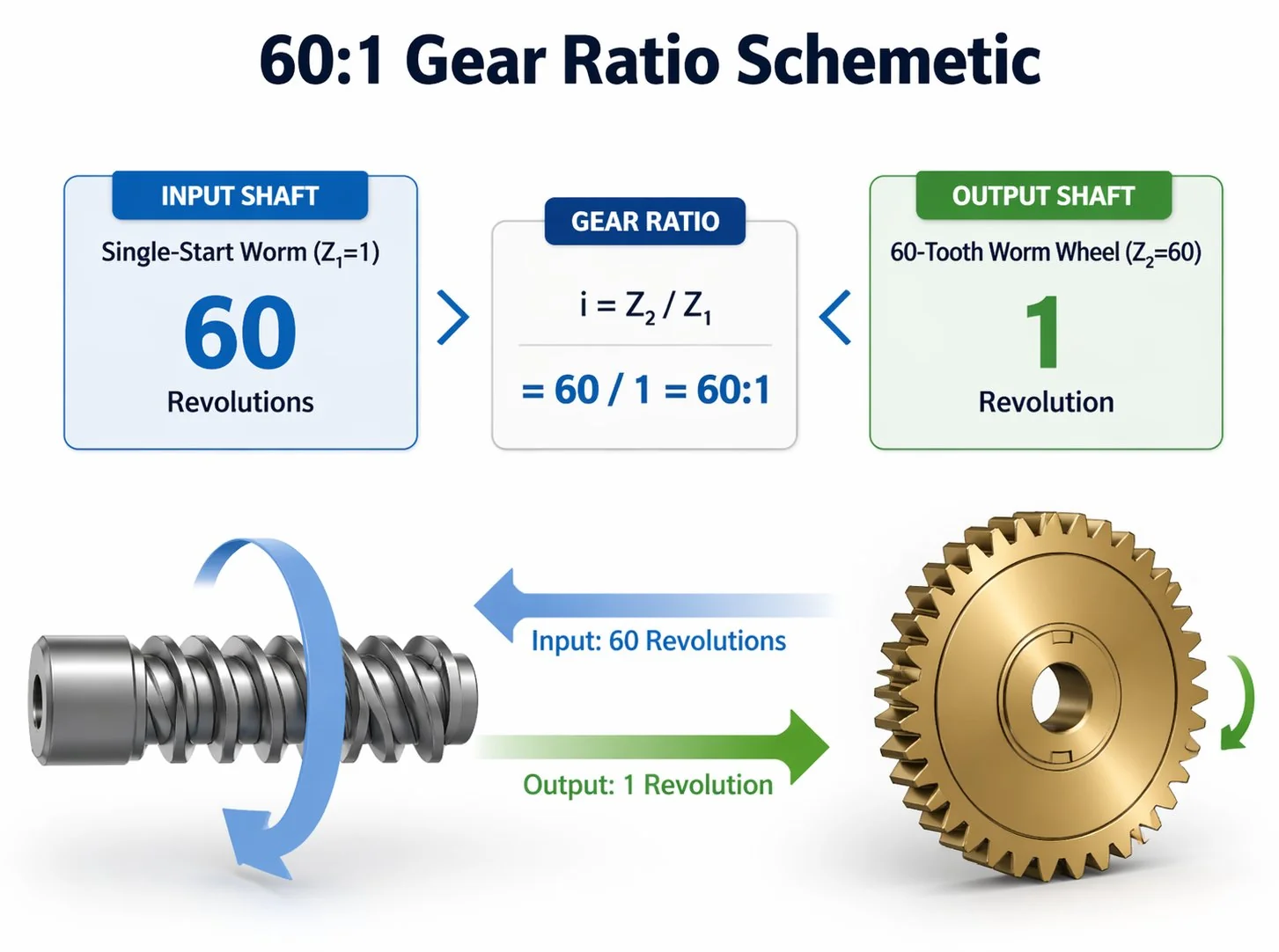
The fundamental worm gear relationship is a = (d₁ + d₂) / 2, where a is the centre distance, d₁ is the worm reference (pitch) diameter, and d₂ is the wheel reference diameter. Both diameters are products of the module and the diameter quotient (q) for the worm, and the module and tooth count (z₂) for the wheel. The equation looks simple but encodes the entire geometric design of the pair. A worm gear with module 4.0, q=10, and z₂=40 produces d₁ = 40 mm, d₂ = 160 mm, and a = 100 mm — which is exactly an ISO standard centre distance. The standardisation is not coincidence; the equation was solved backwards from the preferred series.
ISO preferred series — R10, R20, R40
Centre distance values follow the Renard preferred number series — a geometric progression that produces values evenly spaced on a logarithmic scale. R10 means each value is 1.25× the previous (10√10 ≈ 1.2589). R20 uses 1.12× steps (20√10 ≈ 1.1220). R40 uses 1.06× steps. The finer the series, the more density of available sizes in any given range.
Catalogue worm gear pairs almost always use R10 standard centre distances. Custom pairs can be specified at R20 or R40 values, but require new tooling.
For most industrial worm gear procurement, the R10 series gives the broadest catalogue inventory and the lowest cost. Specifying a non-R10 value when R10 fits forces the supplier into custom production with corresponding lead time and price premium.
The eight standard centre distances explained
Eight centre distance values cover the bulk of industrial worm gear demand: 50, 63, 80, 100, 125, 160, 200, and 250 mm. These are the R10 values from the standard series, and they exist because the geometric progression produces a sensible population of sizes that cover roughly two decades of torque capacity.
50 mm. Small precision worm gear pairs for indexers, servo-driven positioners, and laboratory equipment. Output torque capacity 60 to 90 N·m at module 1.5, ratio 30:1 to 50:1. Smallest catalogue size with broad availability.
63 mm. Light industrial worm gear pairs for small conveyors, agitators, and metering pumps. Output torque 130 to 180 N·m at module 2, ratio 25:1 to 60:1.
80 mm. Medium-light industrial. Belt conveyors at moderate loads, packaging machinery feed drives, light hoist applications. Output torque 220 to 320 N·m at module 2.5 or 3.
100 mm. Most popular industrial size. Conveyor drives, mixer drives, hoist drives, machine tool indexers. Output torque 400 to 600 N·m at module 3 or 4. Roughly 30 percent of all industrial worm gear pairs sold globally are at 100 mm centre distance.
125 mm. Medium-heavy industrial. Larger conveyors, plant ventilation drives, water treatment mixers. Output torque 700 to 1,100 N·m at module 4.
160 mm. Heavy industrial. Cement plant conveyors, mining drives, large hoists. Output torque 1,200 to 2,000 N·m at module 5 or 6.
200 mm. Very heavy industrial. Bulk material handling, large mixer drives, tower crane slewing. Output torque 2,200 to 3,500 N·m at module 6 or 8.
250 mm. Largest standard catalogue size. Heavy hoists, large mining equipment, ship deck machinery. Output torque 3,800 to 6,000 N·m at module 8 or 10. Above 250 mm, custom production typically takes over from catalogue.
A Vietnamese conveyor manufacturer once specified a 90 mm centre distance worm gear pair for a new product line. The number came from a hand calculation — the application required output torque 380 N·m and the engineer estimated a centre distance to match. None of the major suppliers had 90 mm in catalogue stock; quotes came back at custom pricing 850 USD per pair with 8 weeks lead time. A 30-second check against the R10 series would have shown that 90 mm sits between 80 mm and 100 mm in the standard progression — neither on the list. The buyer had unknowingly specified a non-standard size. Re-specification to 100 mm centre distance returned catalogue pricing at 220 USD per pair with 1 week lead time. The 380 N·m torque requirement fit comfortably within the 100 mm capacity envelope of 400 to 600 N·m. Annual saving across the 80-unit production run: 50,400 USD. Always check the proposed centre distance against the R10 standard list before submitting the quote request — if the value is not on the list, ask whether the application truly requires the off-list value.
Centre distance error — impact on meshing performance
Worm gear centre distance error is the deviation between the as-built centre distance (the actual axis-to-axis spacing of the worm and wheel shafts in the assembled pair) and the design value. The error has three primary consequences that all worm gear engineers should be able to estimate quickly.
Backlash. One millimetre of positive centre distance error (worm and wheel further apart than design) increases backlash by roughly 0.4 to 0.6 mm at the wheel rim, depending on module. For a typical 100 mm centre distance pair with module 4, that is a 30 to 50 percent backlash growth. The relationship is approximately linear within the assembly tolerance range. Negative error (closer together) reduces backlash but risks tip-and-root interference and accelerated wear.
Barulho. Centre distance error shifts the gear mesh frequency excitation pattern and produces additional dynamic forces at the contact line. Empirical data from engrenagem sem-fim test rigs shows roughly 3 to 6 dB additional noise at the gear mesh fundamental frequency per millimetre of centre distance error. The increase is most audible at the worm input rotation rate harmonic — a steady whine that varies with load.
Padrão de contato. The visual diagnostic for centre distance error is the bluing test contact pattern. Off-design centre distance shifts the contact band away from the wheel tooth centreline. Positive error shifts contact toward the wheel tooth tips; negative error shifts contact toward the tooth root. Either shift reduces the effective contact area and concentrates load on a thin band, with predictable acceleration of wear.
The diameter quotient q — worm size relative to module
The diameter quotient q is the ratio of worm pitch diameter to module: q = d₁ / m. Standard values run from 4 to 16, with most industrial worm gear pairs falling between 8 and 12.
Higher q means a relatively thicker worm — stiffer, less prone to deflection, but heavier and slightly less efficient. Lower q means a slimmer worm — more efficient and lower inertia, but more deflection-prone under load.
For a given centre distance and module, q determines whether the design feasibility passes or fails. The constraint is a = (d₁ + d₂) / 2 = m(q + z₂)/2, which means specifying a, m, and z₂ leaves q as a derived value: q = 2a/m − z₂. If the calculated q falls outside the range 4 to 16, the design is infeasible at the chosen module and centre distance.
Example: design 100 mm centre distance, module 4, ratio 50:1 with a single-start worm. Then z₂ = 50, and q = 2(100)/4 − 50 = 0. The design is infeasible — the worm pitch diameter would be zero. Increasing the module to 5 gives q = 2(100)/5 − 50 = −10, still infeasible. The right combination is module 3, z₂ = 50, q = 2(100)/3 − 50 = 16.67. Slightly above the typical maximum but workable. A module 2.5 gives q = 30, well above maximum — infeasible the other direction. The best fit is module 3 with z₂ = 50.
Three real centre distance specification cases

The three cases below illustrate three different centre distance decision paths — direct R10 catalogue fit, R20 step due to ratio constraint, and a costly off-standard mistake corrected at re-specification.
Each path is the right answer for its specific application — the procurement skill is recognising which path applies before submitting the quote request.
Case 1 — Korean automotive R10 direct fit
A Korean Tier 1 automotive supplier qualifying a worm gear pair for a power-window actuator started from the application requirements: output torque 8 N·m peak, ratio 35:1, package envelope 60 mm height. Engineering check against R10 series identified 50 mm and 63 mm as the candidates. 50 mm with module 1.5, q=10 gave d₁=15 mm, d₂=85 mm, sum=100, half=50 mm — fit confirmed. 63 mm was oversized for the application. Decision: 50 mm centre distance, module 1.5, single-start worm with 35-tooth phosphor bronze wheel. PPAP first-article on the 50 mm catalogue base passed in 5 weeks. Volume production at 220 USD per pair against 1,200 USD that a custom 55 mm or 58 mm would have cost. Annual saving at 12,000 unit volume: roughly 11.8 million USD. Lesson: when R10 fits, the savings versus custom are not modest — they are transformative.
Case 2 — Japanese precision indexer requires R20
A Japanese semiconductor equipment OEM specified a worm gear pair for a 6-station rotary indexer where positioning repeatability of plus or minus 4 arcseconds was required. The driving constraint was the ratio: exactly 360:1 gives one degree per worm revolution, which simplified the servo controller logic and improved repeatability. With z₁=1 and z₂=360, the wheel pitch diameter at module 2 is 720 mm, and the worm pitch diameter at q=10 is 20 mm. Half the sum is 370 mm — well off any R10 value. The closest R20 value is 355 mm, requiring slight q adjustment to 7.5 or so. Decision: specify centre distance 355 mm exactly (R20), module 2, q=7.5. Cost: 4,400 USD per pair custom production against catalogue infeasibility. Lead time: 11 weeks first article, 6 weeks reorder. The R20 step gave the geometric flexibility R10 lacked. Lesson: when ratio constraints fight R10 standardisation, R20 is the next-cheapest path forward.
Case 3 — Vietnamese conveyor 90 mm specification error
A Vietnamese mid-market conveyor manufacturer specified 90 mm centre distance worm gear pairs for a new product line. The number came from a back-of-envelope calculation matching application output torque 380 N·m. None of the contacted suppliers had 90 mm in catalogue stock — quotes came back at custom pricing 850 USD per pair, 8 weeks lead time, 25-unit minimum order quantity. A 30-second check against R10 series would have shown 90 mm sits between 80 mm and 100 mm — not standard. Engineering review re-specified to 100 mm catalogue, where the 380 N·m torque fit within the 400-600 N·m capacity envelope at module 4. Catalogue pricing returned at 220 USD per pair, 1 week lead time, single-unit minimum. Annual saving across 80 units: 50,400 USD. The original specification cost the buyer 5 weeks of project schedule and almost a year of competitive disadvantage if it had been accepted. Lesson: always check proposed centre distance against R10 standard list before submitting the quote request. Browse redutor de engrenagem helicoidal options that align catalogue centre distance with the R10 standard.
Perguntas frequentes
Q: What centre distance tolerance class should I specify?
For a typical industrial worm gear pair, IT7 according to ISO 286 is the standard. For a 100 mm centre distance, IT7 corresponds to plus or minus 17.5 micrometres of allowed deviation — fine enough for stable backlash and contact pattern, loose enough to be assembly-friendly. IT6 is reserved for precision applications (machine tools, indexing equipment, servo positioners) and corresponds to plus or minus 11 micrometres at 100 mm. IT8 is used for low-load and economical drives and allows plus or minus 27 micrometres. Specifying tighter than IT6 rarely pays back in practice — at IT5 and below, assembly costs grow faster than performance gains.
Q: How does centre distance interact with module choice?
The relationship a = m(q + z₂)/2 ties module and centre distance together through q and z₂. For a fixed ratio (z₂) and required centre distance (a), the module is constrained: m = 2a/(q + z₂). For 100 mm centre distance at 50:1 ratio with q=10, module works out to roughly 3.33 — non-standard. The nearest standard module is 3.0, which forces z₂ to adjust to 56 (giving 56:1 instead of 50:1) or q to adjust to 16.67 (above typical maximum). The interaction is why catalogue centre distances and standard modules tend to fall on compatible combinations — the supply chain has solved the math for the most common cases.
Q: Can I shim a worm gear assembly to correct centre distance?
In principle yes, in practice rarely worthwhile. A precision shim under the worm bearing housing can adjust the centre distance by up to 0.2 to 0.5 mm. The technique is used routinely during assembly to fine-tune contact pattern at first installation. As a field correction for centre distance error discovered after months of service, shimming is less reliable because the wear pattern that has developed is biased toward the original (incorrect) centre distance — shifting to the correct value may not restore proper contact. The better approach is identifying centre distance error early during incoming inspection or commissioning, not after the wear pattern has set.
Q: Why does R10 use the specific values 50, 63, 80, 100, 125, 160, 200, 250 mm?
The Renard preferred series was developed by French engineer Charles Renard in the 1870s as a way to reduce inventory while maintaining reasonable size coverage. R10 means each value is approximately the 10th root of 10 (1.2589) times the previous — a logarithmic progression that gives roughly 25 percent step size per increment. The actual values are rounded to convenient numbers (50 instead of 50.119, 63 instead of 63.096, etc.). The advantage of the geometric progression is that any size requirement can be met within roughly 12 percent by selecting the next-largest standard value, which keeps a small inventory of standard sizes useful across a wide range of applications. The system has been adopted globally and forms the basis of ISO 3, DIN 323, and most national standards for preferred numbers.
Q: How do I measure centre distance on an existing worm gear assembly?
Three methods cover most practical cases. Direct measurement: with the assembly opened, measure axis-to-axis spacing between the worm shaft and wheel shaft using a calliper or precision rule. Useful for casting verification before assembly. Bore-to-bore measurement: with the housing on a CMM, measure the worm-bearing-bore centre coordinate and the wheel-bearing-bore centre coordinate, then compute the distance between them. Most accurate, suitable for incoming inspection. Indirect verification: measure backlash and contact pattern, which both deviate predictably from design centre distance. The third method does not give the centre distance directly but identifies the deviation magnitude. For new pairs, the bore-to-bore CMM check is the gold standard; for in-service pairs, the indirect method is cheaper.
Q: What happens if I specify a centre distance below 50 mm?
R10 series continues below 50 mm at 40, 31.5, 25, 20, 16, 12.5, 10 mm. These miniature centre distances are used for precision instruments, miniature actuators, and laboratory equipment but represent a small market segment with specialised supply. Catalogue availability drops sharply below 50 mm. For 25 to 50 mm range, several Asian catalogue suppliers including KHK and SDP-SI offer standard products. Below 25 mm, custom production is typical. Module choices also become limited at small centre distances — module 1, 1.5, and 2 are realistic; module 0.5 and below require precision instrument manufacturing techniques.
Q: How should centre distance be documented on a drawing?
A complete worm gear pair drawing call-out for centre distance includes: nominal value (e.g., 100 mm), tolerance class (e.g., IT7 from ISO 286), absolute tolerance numbers (e.g., plus or minus 0.0175 mm), and reference standard (e.g., DIN 3974). The full call-out reads “a = 100 mm, IT7 (±0.0175 mm) per DIN 3974, ISO 286.” This single line gives the supplier complete information for both production and inspection. Truncated call-outs (just “a = 100” without tolerance) trigger clarification cycles and risk supplier-default tolerance which may be looser than the application requires.
Centre distance is the geometric anchor of every worm gear pair. The simple equation a = (d₁ + d₂) / 2 hides a complex web of dependencies: module, ratio, diameter quotient, tooth profile, contact pattern, backlash, noise, and load capacity all flow from centre distance choice. The eight R10 standard values from 50 to 250 mm cover roughly 90 percent of industrial demand, and specifying within this list keeps procurement on catalogue pricing and lead times. Off-list specifications (R20 or custom) are sometimes justified by genuine application constraints — exact ratio synchronisation, tight envelope packaging, specialised material requirements — but rarely justified by hand-calculated convenience numbers that happen to fall between standard values. The procurement skill is recognising which is which.
Specifying centre distance for a new worm gear pair?
Send the application requirements — output torque, ratio, envelope constraints, and any non-negotiable dimensions. We will check the proposed centre distance against R10 / R20 standards, suggest the closest catalogue fit, and quote both the catalogue and custom paths — typically within one Korean working day.
Editor: Cxm


