Como funcionam as engrenagens helicoidais — A mecânica em 5 etapas
Uma análise quadro a quadro do que realmente acontece na interface entre os dentes — a física que determina se seu disco rígido funciona frio, silencioso ou se desgasta em três meses.
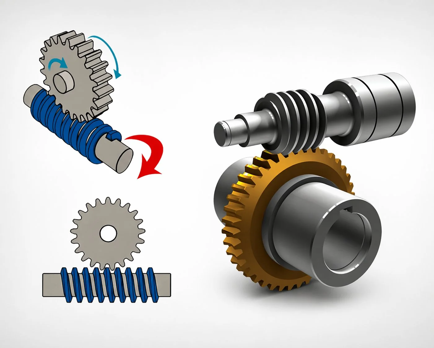
O mecanismo é simples e consiste em cinco etapas: um eixo de entrada gira o parafuso sem-fim, a rosca helicoidal do parafuso sem-fim empurra lateralmente um dente da engrenagem helicoidal, o contato desliza em vez de rolar (este é o princípio físico fundamental), o torque é multiplicado proporcionalmente à relação de redução menos as perdas por atrito e, em ângulos de ataque baixos, a geometria se autotrava, impedindo que a engrenagem helicoidal gire para trás. Todos os outros aspectos de um conjunto parafuso sem-fim e engrenagem helicoidal — calor, ruído, escolha do lubrificante, vida útil — derivam desse ciclo de cinco etapas.
Por que os diagramas estáticos não mostram o que realmente está acontecendo?
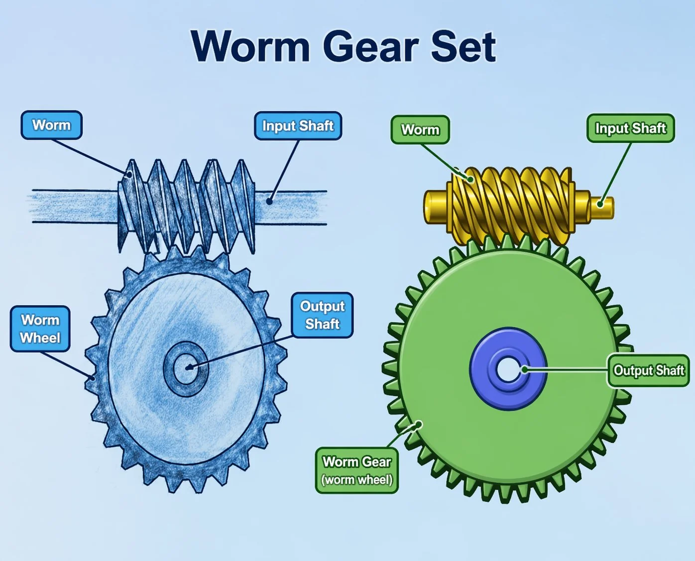
A maioria das explicações sobre a mecânica de engrenagens helicoidais baseia-se em um desenho explodido com setas indicando "entrada" e "saída". Essa visualização está correta, mas é inútil para decisões de projeto. As setas não mostram os quarenta milissegundos de contato entre um dente da engrenagem e a rosca helicoidal, nem a forma como a área de contato migra do flanco dianteiro para o flanco traseiro, nem por que a espessura da película lubrificante logo abaixo do ponto de contato determina se você terá uma transmissão com vida útil de 40.000 horas ou de 4.000 horas.
A seguir, imagine um único dente na engrenagem sem-fim — digamos, o dente 17 de uma engrenagem de 40 dentes — e acompanhe-o durante um ciclo completo de engate enquanto o sem-fim gira. Cada uma das cinco seções abaixo representa uma fase distinta desse ciclo. Visualize essa imagem e o restante do projeto de engrenagens sem-fim — seleção de material, lubrificação, classe de precisão, decisão do ângulo de ataque — se encaixará quase que automaticamente.
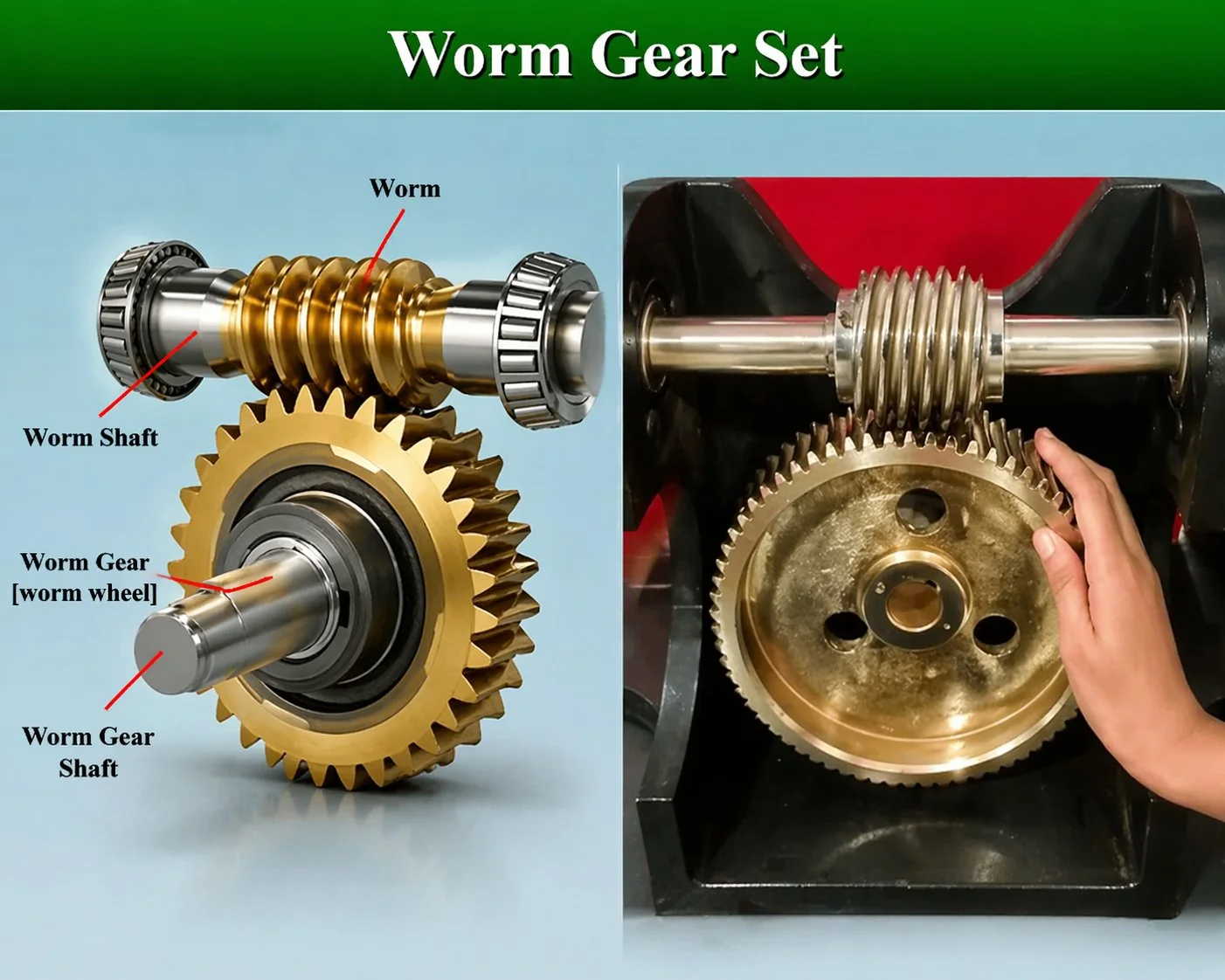
Etapa 1 — O torque de entrada chega ao eixo sem-fim.
Um motor, uma manivela ou uma engrenagem a montante gira o eixo sem-fim. As entradas de motores industriais normalmente variam entre 500 e 3.000 rpm; aplicações de precisão servoacionadas podem operar em rotações mais baixas; sistemas de acionamento direto de alta velocidade ocasionalmente atingem 5.000 rpm. O torque que chega ao eixo é aquele fornecido pelo motor — frequentemente apenas alguns Newton-metros para um acionamento de baixa potência.
Dois fatos sobre o eixo de entrada são importantes para todo o processo subsequente. Primeiro, o próprio sem-fim é uma rosca helicoidal retificada com precisão, e não um dente de engrenagem fresado — uma rugosidade superficial Ra inferior a 0,4 micrômetros é prática padrão em uma unidade de qualidade, pois cada micrômetro de aspereza aumenta o atrito durante a fase de contato deslizante. Segundo, o eixo precisa suportar uma carga axial significativa (veremos o porquê na etapa 3), o que significa que o arranjo do rolamento de entrada não é a configuração radial simples que você usaria em uma transmissão por engrenagens cilíndricas.
Etapa 2 — A rosca engata no dente 17
À medida que a rosca gira, a borda de ataque de uma volta da hélice se aproxima do Dente 17 lateralmente. O engate começa na parte inferior da garganta (a superfície côncava da roda que envolve a rosca) e progride ao longo do flanco do dente em direção à ponta. Em uma rosca sem-fim de garganta única e entrada única, de três a quatro dentes estão engrenados a qualquer momento — o Dente 16 está saindo, o Dente 17 está no ponto máximo de contato, o Dente 18 está entrando e o Dente 19 está se aproximando.
Para uma engrenagem helicoidal de partida única girando a 1.500 rpm, cada dente individual em uma roda dentada de 40 dentes entra em contato uma vez por rotação da engrenagem helicoidal — ou seja, uma vez a cada 40 milissegundos. A duração real do contato é de aproximadamente 12 a 15 milissegundos por ciclo. Durante esses 12 milissegundos, a rosca da engrenagem helicoidal percorre toda a superfície útil do dente, da raiz à ponta, e não o breve contato tangencial que ocorre em um par de engrenagens cilíndricas de dentes retos.
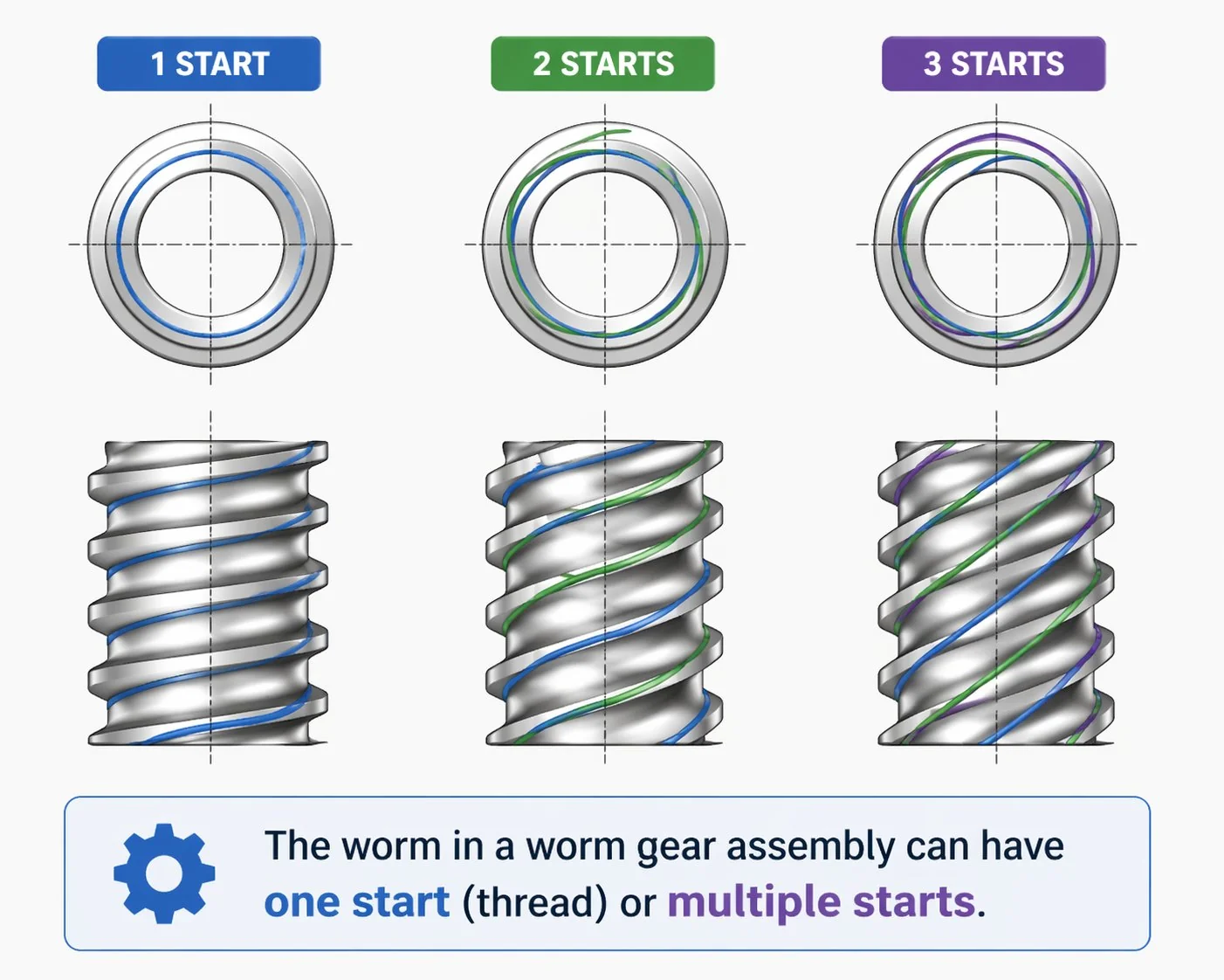
Se a engrenagem sem-fim tiver duas entradas (uma hélice de duas entradas), cada rotação avança a roda em dois dentes em vez de um. O dente 17 ainda apresenta a mesma janela de engate de 12 a 15 milissegundos, mas o ciclo se repete duas vezes por rotação da engrenagem sem-fim. As engrenagens sem-fim com múltiplas entradas existem justamente para equilibrar a relação de transmissão e a eficiência — mais entradas significam maior ângulo de ataque, menor distância de deslizamento por engate e menos calor.
Etapa 3 — O contato deslizante transfere a força.
Eis o fato físico que define tudo o mais sobre um sistema de rosca sem-fim e coroa. Enquanto a rosca sem-fim se apoia no dente 17, o contato é predominantemente deslizante — a rosca helicoidal da rosca sem-fim raspa lateralmente o flanco do dente, transferindo força tangencialmente. Quase não há componente de rolamento. Isso é fundamentalmente diferente de uma engrenagem cilíndrica de dentes retos ou helicoidal, onde o rolamento predomina e o deslizamento é um pequeno movimento secundário próximo à linha primitiva.
Se um cliente me fizer uma pergunta e eu tiver que dar uma resposta que o proteja de 80% das falhas que observei em duas décadas, essa resposta é: "Lembre-se de que o contato é deslizante, não rolante, e escolha o lubrificante de acordo". Óleo genérico para engrenagens helicoidais destruirá uma roda sem-fim de bronze em poucas semanas. O lubrificante precisa manter uma espessura de película que o deslizamento completo não consiga remover, o que é um problema hidrodinâmico muito mais complexo do que um breve contato rolante. ISO VG 460 ou 680 com aditivos seguros para metais amarelos é a opção padrão segura; abaixo de 70 °C de temperatura do cárter, você pode usar óleo mineral; acima disso, use óleo sintético PAO ou PAG.
Três componentes de força em cada contato.
Durante o contato deslizante, três componentes de força atuam no dente da roda e três componentes iguais e opostos atuam na rosca sem-fim. Compreendê-las é fundamental para a seleção de rolamentos e o projeto de eixos.
A força axial no eixo sem-fim é o que pega os projetistas iniciantes desprevenidos. Em uma transmissão de 40:1, que transmite 50 N·m na roda, o empuxo axial no eixo sem-fim pode facilmente ultrapassar 800 N. Um simples arranjo com rolamentos de esferas de ranhura profunda, que seria perfeitamente adequado para uma transmissão por engrenagem helicoidal, se desintegrará em menos de um ano em uma caixa de engrenagens sem-fim. Rolamentos de rolos cônicos ou pares de rolamentos de contato angular em configuração back-to-back são a solução padrão.
Etapa 4 — O torque é multiplicado na saída da roda.
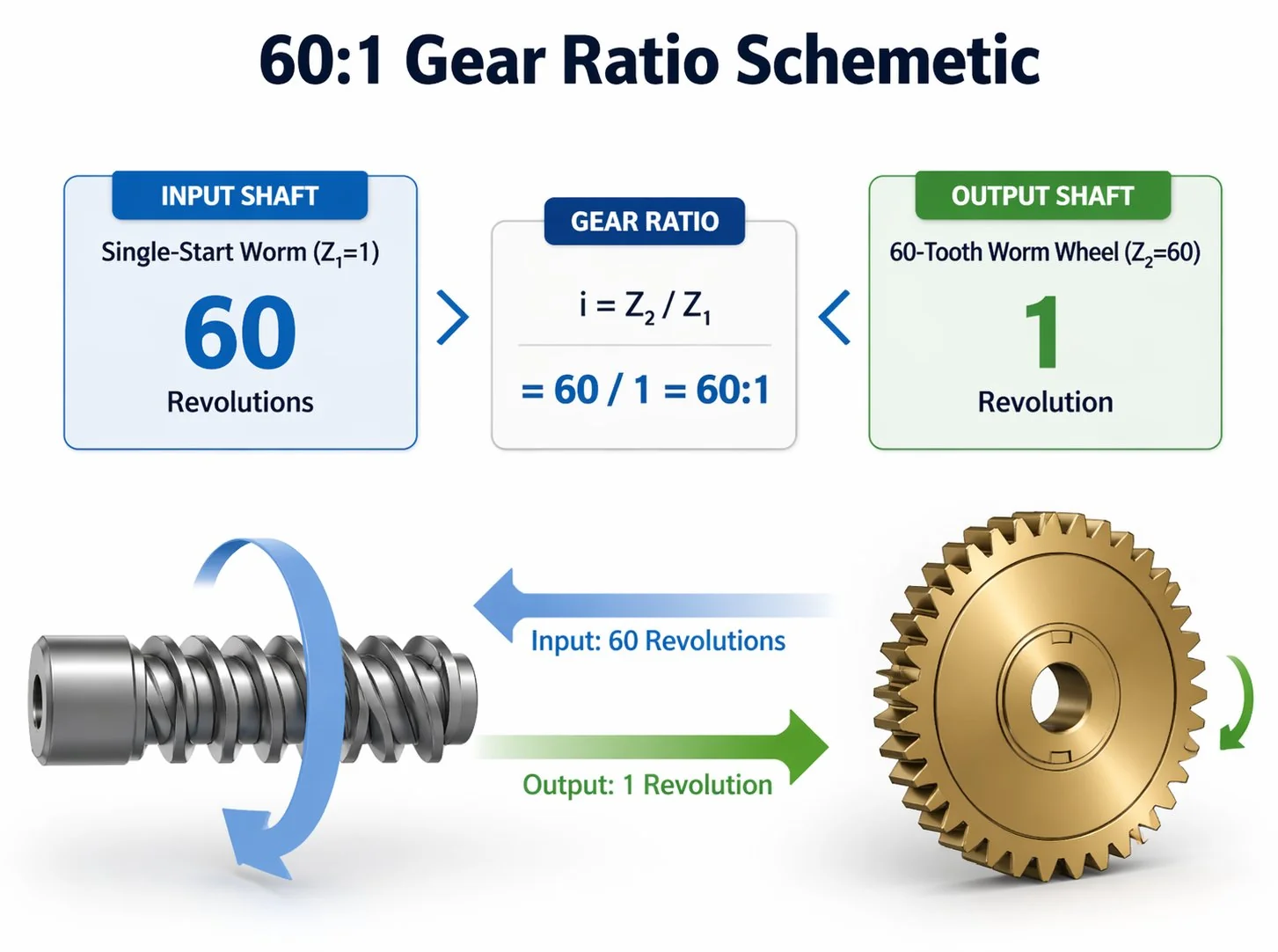
Assim que a componente da força tangencial atinge o dente 17, ela é convertida em torque no eixo de saída através do braço de alavanca do raio da roda. O cálculo é simples: uma rosca sem-fim de entrada única, engrenando com uma roda de 40 dentes, gira a roda exatamente 1/40 de uma revolução por rotação da rosca sem-fim. A velocidade de entrada é dividida por 40, o torque de entrada é multiplicado por 40 — menos as perdas por atrito.
As perdas por atrito são o problema. O contato deslizante dissipa uma fração significativa da potência de entrada na forma de calor. Um inversor de fase com um ângulo de avanço de 4 graus e um lubrificante bem escolhido opera com uma eficiência de aproximadamente 60 a 65%. Um inversor de fase com quatro estágios e um ângulo de avanço de 16 graus eleva essa eficiência para 88 a 92% — mas ao custo de reduzir a relação por estágio em um fator de quatro. A relação é geométrica; não é possível ter simultaneamente a relação máxima e a eficiência máxima no mesmo conjunto.
A fórmula de eficiência com a qual todo projetista eventualmente se depara é η = tan(λ) / tan(λ + φ), onde λ é o ângulo de inclinação da rosca sem-fim e φ é o ângulo de atrito do contato (tipicamente de 5 a 8 graus para aço sobre bronze bem lubrificado, de 10 a 15 graus para lubrificação deficiente ou condições de emergência de funcionamento a seco).
Ao inserir os valores, a relação de compromisso torna-se óbvia. Com λ = 4 graus e φ = 6 graus, a eficiência é de cerca de 40%. Com λ = 12 graus, mantendo o mesmo ângulo de atrito, a eficiência sobe para 67%. Com λ = 25 graus, a eficiência atinge 80%. Para uma explicação mais detalhada com exemplos práticos, consulte nosso artigo complementar sobre relação de engrenagem helicoidal e cálculos.
Etapa 5 — O travamento automático mantém a posição quando a entrada para de funcionar.
A rosca sem-fim completa sua rotação, o motor de entrada para e o dente 17 deixa de ser acionado. O que acontece a seguir é o que torna a engrenagem sem-fim fundamentalmente diferente de qualquer outra família de engrenagens: nada. A roda não gira para trás, a carga não se desloca para baixo, a transmissão simplesmente se mantém.
O travamento automático ocorre quando o ângulo de ataque da rosca sem-fim é inferior a aproximadamente 5 a 6 graus. Nesses ângulos rasos, o atrito estático no contato dos dentes excede a força que a roda carregada pode exercer sobre a rosca sem-fim para empurrá-la lateralmente. O acionamento é geometricamente incapaz de sofrer acionamento reverso pelo lado de saída. Essa é a propriedade que permite a utilização de pares de rosca sem-fim e coroa em elevadores, atuadores de válvulas, guinchos, posicionadores de antenas e mecanismos de freio de estacionamento — todas as aplicações em que um acionamento reverso não intencional seria perigoso ou dispendioso.
Algumas precauções importantes a serem consideradas. O travamento automático é geométrico, não absoluto. A vibração pode fazer com que a carga caia. A película lubrificante altera o coeficiente de atrito — uma transmissão que trava automaticamente a frio pode começar a cair lentamente quando quente. Acima de um ângulo de avanço de 12 graus (típico de transmissões com múltiplas partidas), o travamento automático desaparece completamente e a roda pode girar livremente para trás. Nunca use o travamento automático como dispositivo de segurança principal em aplicações com queda de carga; especifique um freio mecânico separado e considere o travamento automático como um recurso auxiliar útil.
Um exemplo prático que você pode reproduzir em um guardanapo.
Considere uma aplicação industrial típica: uma talha elétrica de corrente levantando uma carga de 200 kg em um tambor com raio de 50 mm. O cálculo segue diretamente os cinco passos acima.
Um motor de 0,75 kW a 1400 rpm de entrada produz uma saída de tambor de elevação de 35 rpm com 98 N·m de torque, elevando a carga de 200 kg com segurança, enquanto a propriedade de travamento automático a mantém suspensa no ar quando o operador solta o controlador. Observe como cada número na cadeia depende da estimativa correta da eficiência — e a eficiência depende do ângulo de avanço, que por sua vez depende da relação de transmissão escolhida. O ciclo de cinco etapas é interligado; não é possível ajustar um parâmetro sem afetar os outros.
O que os designers mais frequentemente erram
Tratar a eficiência como uma constante. A eficiência de 60% publicada na ficha técnica de um catálogo é o valor nominal para a carga e velocidade nominais. Ao operar o mesmo inversor com um décimo da carga, a porcentagem frequentemente cai abaixo de 40%, pois a película lubrificante é mais espessa do que o necessário e o torque de atrito predomina sobre o torque útil reduzido. Sempre utilize o ponto de operação real, e não o valor nominal divulgado.
Dimensionar o motor de entrada sem atrito na corrente. A tentação é pegar o torque de saída, dividir pela relação de transmissão e chamar isso de torque do motor. Esse cálculo dá a resposta errada porque ignora o atrito. Sempre inclua o divisor de eficiência: torque de entrada = torque de saída ÷ (relação de transmissão × eficiência).
Ignorando a carga axial no eixo de entrada. A falha mecânica mais comum em adaptações onde um redutor helicoidal foi substituído por um redutor de rosca sem-fim, mantendo-se os rolamentos originais, é causada por um arranjo de rolamentos exclusivamente radiais. O componente axial acaba por desgastar esses rolamentos prematuramente.
Supondo que o travamento automático seja permanente. O travamento automático depende de um coeficiente de atrito que varia com a temperatura, a condição do lubrificante e a vibração. Uma transmissão que trava automaticamente logo após sair da oficina pode apresentar esse problema um ano depois, quando o óleo se torna mais fino devido ao calor e ao uso. Especifique um freio para qualquer travamento crítico em termos de segurança.
Utilizando lubrificante genérico. O óleo para engrenagens helicoidais é um produto especializado. O contato deslizante exige uma película mais espessa do que o contato rolante, e a compatibilidade com metais amarelos é obrigatória, pois a maioria das engrenagens helicoidais são de bronze. Aditivos EP de enxofre ativo, comuns em óleos diferenciais, corroem o flanco de bronze acima de 70 graus Celsius. Sempre use um óleo classificado para essa aplicação — e, se não tiver certeza de qual especificação é adequada para o seu ciclo de trabalho, solicite um orçamento. revisão das especificações de lubrificação da mesa de engenharia antes do primeiro abastecimento de óleo.
Perguntas frequentes
P: Por que uma engrenagem sem-fim precisa de um rolamento de encosto no eixo de entrada?
O contato deslizante entre a rosca sem-fim e o dente da engrenagem gera uma componente de força axial ao longo do eixo sem-fim. Em uma transmissão industrial típica, esse empuxo axial pode variar de algumas centenas a vários milhares de Newtons, dependendo do torque e do ângulo de inclinação. Um simples rolamento de esferas radial não consegue suportar essa carga por muito tempo sem falhar, portanto, rolamentos de rolos cônicos ou pares de contato angular são padrão em eixos sem-fim.
P: Uma engrenagem sem-fim pode funcionar a seco, mesmo que brevemente?
De forma alguma significativa. O contato deslizante depende de uma película lubrificante contínua para evitar o atrito metal com metal. Em segundos após o funcionamento a seco, o ângulo de atrito sobe dos normais 6 a 8 graus para 15 graus ou mais, a eficiência da transmissão cai drasticamente, a roda de bronze sofre atrito e a temperatura da superfície aumenta repentinamente. Transmissões que perdem óleo em serviço geralmente são irrecuperáveis — os dentes da roda precisarão ser substituídos mesmo que o eixo sem-fim sobreviva.
P: Por que o verme é sempre o condutor, e nunca o elemento conduzido?
Em configurações autoblocantes (ângulo de avanço inferior a 5 ou 6 graus), a roda não consegue acionar o parafuso sem-fim porque o atrito estático no ponto de contato excede a força de reversão. Em configurações não autoblocantes (múltiplas entradas, ângulo de avanço maior), a roda consegue acionar o parafuso sem-fim, mas o sistema é muito menos eficiente nessa direção, pois o atrito atua contra o movimento tanto para frente quanto para trás. A direção natural de energia da geometria é o parafuso sem-fim acionando a roda.
P: Quanto calor uma caixa de engrenagens helicoidais realmente gera?
Depende inteiramente do ponto de operação. Um inversor de frequência com potência de entrada de 1 kW e eficiência de 60% dissipa 400 W como calor no cárter de óleo. Em uma pequena carcaça selada de ferro fundido, isso é suficiente para elevar a temperatura do cárter de 30 a 50 graus Celsius acima da temperatura ambiente em regime permanente. Para inversores de frequência operando acima de 5 kW em regime contínuo, o resfriamento suplementar (aletas, ventilador ou resfriador de óleo) torna-se obrigatório, e não opcional. A dissipação de calor é frequentemente a principal restrição para operação contínua. redutor de engrenagem helicoidal Dimensionamento — não torque, não vida útil do rolamento, mas sim a rapidez com que a carcaça consegue dissipar o calor residual para o ambiente.
P: A relação de transmissão da engrenagem sem-fim muda se eu alterar o material da engrenagem sem-fim?
Não, a relação é puramente geométrica — número de dentes da engrenagem dividido pelo número de voltas da rosca sem-fim. O material afeta a capacidade de carga, a vida útil e a eficiência, mas não a relação cinemática entre a velocidade de entrada e a de saída. Um conjunto com relação de 40:1 permanece com essa relação, independentemente de a rosca sem-fim ser de aço-liga SCM415 temperado ou de aço macio não temperado; apenas a engrenagem de bronze sofrerá desgaste diferente nos dois casos.
P: Qual a faixa de rotações por minuto (RPM) razoável para uma entrada de eixo sem-fim?
Para acionamentos industriais, a faixa de operação ideal é de 500 a 3.000 rpm de entrada. Abaixo de 500 rpm, a película lubrificante tem dificuldade em se formar, pois a velocidade de deslizamento relativa é muito baixa para que os efeitos hidrodinâmicos se manifestem. Acima de 3.000 rpm, a taxa de geração de calor excede a capacidade de dissipação de uma carcaça selada típica, tornando necessário o uso de sistemas de refrigeração. Acionamentos especiais de alta velocidade podem operar a 5.000 ou 6.000 rpm com circulação forçada de óleo, mas são a exceção, não a regra.
P: Por que uma engrenagem sem-fim parece diferente de uma engrenagem cilíndrica quando você a gira manualmente?
Isso ocorre porque a maior parte da resistência que você sente é atrito de deslizamento, e não apenas inércia. Uma engrenagem cilíndrica gira relativamente livre depois de iniciada a rotação, pois o contato de rolamento tem baixo atrito. Um conjunto de rosca sem-fim e coroa parece pesado e amortecido, quase como se houvesse um arrasto viscoso, porque cada grau de rotação envolve a rosca sem-fim varrendo as superfícies dos dentes da coroa. O teste de rotação manual é, na verdade, uma verificação inicial útil para saber se o lubrificante é adequado — se for muito espesso, a transmissão fica rígida; se for muito fino, você pode ouvir um leve contato mecânico através da carcaça.
Uma vez que o modelo de cinco etapas esteja claro, todas as outras decisões de engenharia em um par de parafuso sem-fim e coroa se relacionam diretamente a ele. A seleção do material diz respeito a quais dois metais podem suportar a fase de deslizamento. A lubrificação visa manter a película lubrificante durante o contato. O ângulo de ataque é o fator de equilíbrio entre a profundidade da relação de transmissão e a perda de eficiência. O travamento automático ocorre quando o ângulo de atrito excede o ângulo de ataque. A dissipação de calor é o que limita a frequência com que o ciclo pode ser executado.
Para equipes de projeto de OEMs coreanos e japoneses que estejam elaborando sua primeira especificação de transmissão por parafuso sem-fim, nossa equipe de engenharia em Ansan pode analisar seu ciclo de trabalho, recomendar um ângulo de ataque e um par de materiais, e fornecer uma cotação compatível. conjuntos de engrenagens helicoidais de entrada única e de múltiplas entradas Em nosso catálogo padrão. Os desenhos são revisados sob acordo de confidencialidade antes que qualquer orçamento seja enviado.
Está com dificuldades para decidir entre o equilíbrio entre ângulo de ataque e eficiência?
Envie-nos o torque de saída, a rotação de entrada e se você precisa de travamento automático. Nossa equipe de engenharia fará o cálculo em cinco etapas para você, recomendará uma relação de transmissão e um ângulo de avanço, e fornecerá o preço do conjunto de engrenagem helicoidal e coroa compatíveis — geralmente dentro de um dia útil na Coreia.
Editor: Cxm


