Korea Ever-Power · Application Engineering Guide
Worm and Worm Wheel for Elevator and Lift Systems — Safety Guide
An elevator car carrying 8 passengers weighs 2,400 kg suspended by a steel rope wrapped around a traction sheave. Between the motor and that sheave sits a worm gear pair. If the pair allows reverse rotation, the car falls. Four verification steps — static, dynamic, vibration, and brake redundancy — determine whether the pair holds under every condition the building will ever produce.
Elevator worm gear pairs must pass a four-step self-locking verification: (1) static lock — lead angle γ must be at least 2 degrees below the static friction angle ρ_s; (2) dynamic lock — γ must be below the dynamic friction angle ρ_d that applies during motor cut-off deceleration; (3) vibration lock — γ must be below the reduced effective friction angle under building vibration (ρ_v ≈ 60 to 80 percent of ρ_s); and (4) brake redundancy — a separate mechanical brake must provide independent holding regardless of worm gear locking status. Elevator standards (EN 81-20, ASME A17.1, Korean KS B 6210) require all four conditions to be met simultaneously. Freight elevators use standard single-start pairs at lead angle 3 to 4 degrees. Passenger elevators increasingly specify duplex worm gear pairs for near-zero backlash, which eliminates the perceptible jolt at direction reversal and produces a smoother ride quality. Elevator machine room noise limits (typically 55 to 65 dB(A)) require ground worm surface finish of Ra 0.4 µm or better.
Why elevators use worm gear traction machines
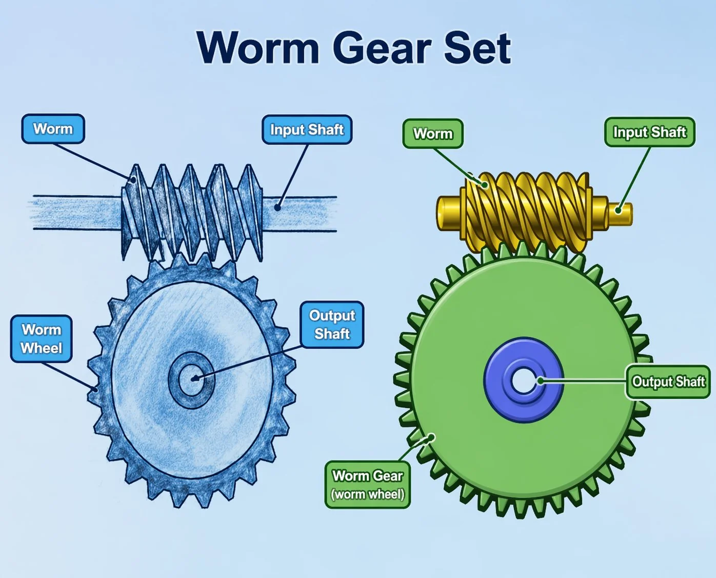
Elevators in buildings up to roughly 30 floors and speeds up to 2.5 m/s predominantly use geared traction machines — a worm gear pair between the motor and the traction sheave. Above 30 floors or 2.5 m/s, gearless permanent-magnet direct-drive machines take over for efficiency and speed. But for the vast majority of the global elevator market — residential buildings, offices up to 15 floors, hospitals, freight elevators, goods lifts, parking lifts — the worm gear traction machine remains the standard.
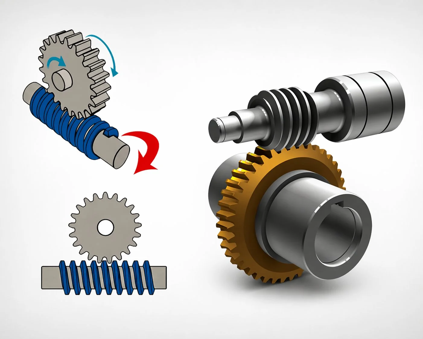
The worm and worm wheel provides mechanical load-holding independent of electrical power or brake condition. If both power and brake fail, the self-locking geometry alone prevents the car from falling.
A single worm gear stage at 30:1 to 60:1 reduces a 1,750 RPM motor to the 30 to 60 RPM sheave speed required for 1.0 to 1.75 m/s car travel — without needing a multi-stage transmission or a large-diameter direct-drive motor.
Worm gear traction machines have operated in buildings since the early 1900s. Standards, installation procedures, and maintenance practices are mature and universally understood by elevator technicians.
The efficiency trade-off (worm gear traction at 45 to 55 percent versus gearless direct-drive at 85 to 95 percent) translates to higher electricity consumption per ride. For a typical 10-floor office building elevator making 200 trips per day, the energy difference is approximately 15 to 25 kWh per day — roughly 3,000 to 5,000 USD per year in Korean electricity costs. Gearless machines save this energy but cost 3 to 5 times more in capital. Below 15 floors, the payback period for gearless typically exceeds 10 years, making the worm gear traction machine the economically rational choice.
Four-step self-locking verification protocol for elevator worm gear pairs
Elevator self-locking verification is more demanding than any other worm gear application because four progressively stricter conditions must all be met. Each step catches a failure mode that the previous step misses. The four-step protocol below is the complete verification framework — passing all four steps is the minimum requirement for any elevator worm gear pair.
A pair that passes Steps 1 and 2 but fails Step 3 will eventually creep under building vibration. A pair that passes Steps 1 through 3 but lacks Step 4 brake redundancy violates every modern elevator code.
Verify: γ ≤ ρ_s − 2°
ρ_s = static friction angle (5-8° for steel-bronze with grease)
Test: Loaded car at rest, motor de-energised, 4-hour hold. Zero creep = pass.
Verify: γ ≤ ρ_d
ρ_d = dynamic friction angle (3-5° with oil film at operating temp)
Test: Running car, motor power cut at full speed. Car decelerates to stop without backward motion.
Verify: γ ≤ ρ_v (= 0.6 to 0.8 × ρ_s)
Building vibration from traffic, wind, HVAC reduces effective friction intermittently.
Test: 24-hour static hold in occupied building. Zero cumulative creep.
Mandatory regardless of Steps 1-3 result.
Spring-applied, electrically-released brake on motor shaft. Must independently hold 125% of rated load.
Code: EN 81-20 §5.6.2 / ASME A17.1 / KS B 6210.
Why Step 3 matters most in practice. Steps 1 and 2 are straightforward for any properly specified single-start worm gear pair at lead angle 3 to 4 degrees. Step 3 — vibration self-locking — is the step that catches borderline designs. A building transmits vibration from multiple sources: road traffic, HVAC systems, wind-induced sway, construction activity on adjacent sites. Each vibration pulse momentarily reduces the effective friction at the worm-wheel contact, and each pulse allows a microscopic amount of creep. Over hours, the cumulative creep can become measurable — the car drifts downward by 1 to 3 mm per hour without any visible cause. In a passenger elevator, this drift misaligns the car floor with the landing sill, creating a trip hazard. In a freight elevator, the drift changes the loading height and may trigger load-cell alarms. Step 3 verification requires a lead angle at least 2 degrees below ρ_v (the vibration-reduced friction angle), which typically means lead angle below 3 degrees for standard steel-on-bronze with grease lubrication.
A Korean building management company reported intermittent floor-levelling errors on a 12-floor passenger elevator installed in 2019 — the car would park 2 to 4 mm below the landing sill after holding at a floor for more than 10 minutes. Maintenance inspections found the brake in good condition (spring force measured at 115 percent of specification) and the motor controller functioning normally. The investigation identified the root cause as vibration-induced creep at the worm gear pair. The worm lead angle was 4.2 degrees. The static friction angle with the installed grease was 5.8 degrees — giving 1.6 degrees of static margin (Step 1 pass). The dynamic friction angle was 4.5 degrees — giving 0.3 degrees of dynamic margin (Step 2 marginal pass). The vibration-reduced friction angle ρ_v was estimated at 3.8 degrees (0.65 × 5.8) — placing γ = 4.2° above ρ_v = 3.8° by 0.4 degrees. Step 3 failed. The building sat on a major road with continuous bus and truck traffic generating measurable floor vibration at 8 to 15 Hz. The solution was replacing the worm gear pair with a lower lead angle specification: γ = 2.8 degrees (q increased from 10 to 14 at the same module), providing 1.0 degree of margin below ρ_v. Replacement cost: 2,800 USD including installation. Post-replacement monitoring over 6 months: zero creep at any floor hold duration up to 2 hours. Lesson: Step 3 vibration verification is not theoretical — it catches real failures that Steps 1 and 2 approve.
Duplex worm gear pairs for passenger elevator ride quality
Standard worm gear pairs have measurable backlash — typically 8 to 20 arcmin at the output shaft. In an elevator traction machine, backlash translates to a perceptible jolt when the car changes direction (from upward deceleration to downward acceleration, or vice versa at the levelling phase). The jolt is felt by passengers as a brief bump or shudder — physically harmless but perceptually unpleasant, especially in premium office and residential buildings where ride quality is a selling point.
A duplex worm gear pair solves this by using a worm with slightly different lead on the two tooth flanks. The lead difference allows the centre distance to be adjusted via axial shimming — as the worm shifts axially, one flank tightens against the wheel while the other loosens. At the correct shim setting, both flanks are in simultaneous contact: zero backlash.
The cost premium for a duplex worm gear pair over a standard pair is 50 to 80 percent — justified in passenger elevators where ride quality affects tenant satisfaction and building value. Freight elevators and goods lifts rarely justify duplex specification because the operators are unconcerned with ride comfort.
Maintenance implication. As the duplex worm wheel wears over years of service, the zero-backlash condition drifts. Re-shimming (adjusting the worm axial position by 0.02 to 0.05 mm) restores zero backlash. The re-shimming interval is typically every 3 to 5 years for passenger elevators making 200 to 400 trips per day. A skilled elevator technician completes the re-shimming in approximately 2 hours — a routine maintenance task that preserves the ride quality premium for the life of the traction machine.
Machine room noise and worm gear surface finish specification
Elevator machine rooms in residential buildings sit directly above the top-floor apartments. The worm gear traction machine is the primary noise source in the room. Korean building noise standards (KS F 2812) limit machine room noise to 50 to 60 dB(A) depending on building class, and structural-borne noise transmitted to apartments below must not exceed 35 dB(A). These limits require the worm gear pair to operate quietly — which means controlling the two primary noise sources: gear mesh frequency excitation and bearing noise.
Gear mesh noise scales directly with worm surface roughness. A hobbed-only worm at Ra 1.6 µm typically produces 65 to 72 dB(A) at 1 metre in a traction machine at rated speed. A ground worm at Ra 0.4 µm reduces this to 55 to 62 dB(A) — an 8 to 10 dB(A) improvement from surface finish alone. For premium passenger elevators, a lapped worm at Ra 0.2 µm further reduces noise to 50 to 55 dB(A). The surface finish specification is therefore not a mechanical performance choice (all three finishes deliver adequate torque capacity) but a noise performance choice driven by the building class and apartment proximity.
Friction coefficient consistency. An equally important reason for specifying ground or lapped finish is friction coefficient stability. The self-locking verification in Step 3 assumes a known friction angle — and the friction angle depends on surface roughness. A hobbed worm at Ra 1.6 µm has a wider friction coefficient range (0.06 to 0.14) than a ground worm at Ra 0.4 µm (0.04 to 0.08). The wider range means the worst-case friction angle is lower and the self-locking margin must be larger to compensate. A ground finish narrows the uncertainty band and allows a slightly more aggressive lead angle — or equivalently, the same lead angle gives more reliable self-locking margin.
Three elevator worm gear pair specification cases
Case 1 — Korean factory freight elevator: 3-tonne, 5 floors, standard pair
A Korean automotive parts manufacturer specified a worm gear pair for a 3-tonne freight elevator serving a 5-floor factory building. Car speed: 0.75 m/s. Sheave diameter: 480 mm. Motor: 15 kW, 1,750 RPM. Required ratio: 42:1 (output 42 RPM). Worm gear pair: single-start, module 5, centre distance 160 mm, q = 12, lead angle 3.0 degrees. Self-locking verification: ρ_s = 6.2 degrees (grease lubrication), margin 3.2 degrees (Step 1 pass). ρ_d = 4.8 degrees, margin 1.8 degrees (Step 2 pass). ρ_v = 3.7 degrees (factory building, moderate vibration from press lines), margin 0.7 degrees (Step 3 pass). Separate spring-applied brake rated at 4,500 N·m (Step 4 pass). Material: case-hardened 16MnCr5 worm ground Ra 0.6 µm, centrifugal-cast phosphor bronze CuSn12Ni wheel. Machine room noise measured at 58 dB(A) — within the 65 dB(A) industrial building limit. Cost per pair: 1,850 USD. Standard pair, standard installation, standard maintenance — the workhorse specification for Korean factory freight elevators.
Case 2 — Japanese residential passenger elevator: 10-person, duplex for ride quality
A Japanese elevator manufacturer specified a duplex worm gear pair for a premium 12-floor residential building in Osaka. Car capacity: 10 persons (750 kg rated). Car speed: 1.6 m/s. The building developer required “grade A ride quality” — no perceptible jolt at direction changes, machine room noise below 52 dB(A), and structural-borne noise below 30 dB(A) in apartments directly below the machine room. Worm gear pair: duplex single-start, module 4, centre distance 125 mm, q = 14, lead angle 2.6 degrees. Lapped to Ra 0.2 µm for minimum noise. Backlash at delivery: 0.3 arcmin (effectively zero). Self-locking margin against vibration: 1.2 degrees (building is inland, low traffic vibration, residential quiet zone). Machine room noise: 51 dB(A) at rated speed. Structural-borne noise in apartment below: 28 dB(A). Both within specification. Cost per pair: 3,400 USD (duplex + lapped premium). Re-shimming scheduled at Year 4 and Year 8 of the expected 20-year traction machine service life. Browse elevator worm gear reducer options for residential and commercial building applications.
Case 3 — Vietnamese hospital bed lift: 2-tonne, extended static hold, vibration concern
A Vietnamese hospital equipment contractor specified a worm gear pair for a bed lift in a 6-floor provincial hospital. The lift carried patients on wheeled beds between the emergency entrance (ground floor) and the surgical floor (4th floor). Critical requirement: the car must hold position at any floor for extended periods — a surgical emergency may keep the lift stationary with a patient on board for 30 minutes to 2 hours while the surgical team prepares. Car weight with bed and patient: 2,000 kg maximum. Speed: 0.5 m/s (bed stability). Worm gear pair: single-start, module 4, centre distance 100 mm, q = 14, lead angle 2.6 degrees. The q = 14 specification gave a relatively fat worm with low lead angle — prioritising self-locking margin over efficiency. Self-locking verification: ρ_s = 5.8 degrees, margin 3.2 degrees (Step 1). ρ_d = 4.2 degrees, margin 1.6 degrees (Step 2). ρ_v = 3.5 degrees (hospital building on a busy road), margin 0.9 degrees (Step 3). Extended static hold test: 4-hour loaded hold with ambient vibration measurement confirmed zero creep. Brake: spring-applied, 125 percent rated. Material: standard case-hardened worm ground Ra 0.4 µm, phosphor bronze wheel. Cost per pair: 1,200 USD. Commissioned with full four-step verification report for hospital accreditation audit documentation.
Често задавани въпроси
Q: What is the typical service life of an elevator worm gear pair?
Elevator traction machine worm gear pairs are designed for 15 to 25 years of service at typical duty cycles (200 to 400 trips per day for passenger, 50 to 150 trips per day for freight). The bronze wheel is the wear element — it typically requires replacement once during the traction machine service life (at roughly 10 to 15 years). The steel worm survives the full machine life. Annual backlash measurement tracks wear progression: plan wheel replacement when backlash reaches 1.5 times the delivery certificate value. For duplex pairs, re-shimming at 3 to 5 year intervals maintains zero-backlash ride quality between wheel replacements.
Q: Can a worm gear elevator be modernised to gearless without replacing the shaft?
In most cases, modernising from worm gear to gearless requires replacing the entire traction machine assembly — the motor, gear pair, sheave, and machine base are typically integrated into a single frame. The shaft dimensions, mounting positions, and sheave diameter are different between geared and gearless machines. However, for buildings where the machine room dimensions and rope arrangement can accommodate a gearless machine, the modernisation delivers significant energy savings (40 to 50 percent reduction in electricity per ride) and improved ride quality. The decision is evaluated on a per-building basis considering elevator speed, building height, daily trip count, and remaining building service life. For buildings below 8 floors with fewer than 100 trips per day, the payback on gearless modernisation rarely justifies the cost.
Q: How does the worm gear pair affect elevator energy efficiency rating?
ISO 25745-2 classifies elevator energy efficiency from Class A (most efficient) to Class G (least efficient). Worm gear traction machines typically achieve Class D to E rating due to the 45 to 55 percent gear efficiency. Gearless machines achieve Class A to B. The gear pair efficiency is the largest single contributor to the energy class gap. Within the worm gear category, the difference between a well-specified pair (ground finish, optimised lubrication, correct lead angle) and a basic pair can be 5 to 8 percentage points of efficiency — potentially shifting the elevator from Class E to Class D. While this does not change the fundamental gear-type efficiency gap, it does reduce annual electricity costs by 10 to 15 percent within the worm gear machine category.
Q: What lubrication does an elevator worm gear pair require?
Elevator worm gear traction machines are typically oil-bath lubricated (not sealed grease) because the continuous duty and heat generation require active cooling by the oil. The oil specification is typically ISO VG 320 or VG 460 synthetic PAG (polyalkylene glycol) — selected for thermal stability, low friction coefficient, and compatibility with phosphor bronze. Oil changes are scheduled every 3 to 5 years based on oil analysis (viscosity, acid number, water content). The oil level and condition should be checked at every annual maintenance visit. Using mineral oil instead of synthetic PAG increases the friction coefficient and reduces the self-locking margin — verify that the four-step self-locking verification passes with the actual installed oil, not just the factory-fill oil.
Q: Are worm gear elevators still being installed in new buildings?
Yes — in large numbers. While gearless machines dominate premium high-rise construction (above 15 floors), worm gear traction machines remain the standard for the global majority of new elevator installations: residential buildings 4 to 12 floors, small offices, hospitals, schools, parking lifts, goods lifts, and freight elevators. In Korea alone, thousands of worm gear traction machines are installed annually. The technology is mature, cost-effective, and fully compliant with current elevator codes. The trend toward gearless is real but gradual — worm gear machines will remain in production and in service for decades to come.
Q: How is floor-levelling accuracy affected by worm gear backlash?
Standard worm gear pairs with 10 to 15 arcmin backlash produce floor-levelling accuracy of plus or minus 5 to 10 mm at the car sill — adequate for most commercial and residential elevators where code requires plus or minus 10 mm. Duplex pairs with near-zero backlash improve this to plus or minus 2 to 3 mm, beneficial for hospital bed lifts (smooth bed-to-floor transition) and freight elevators with forklift access (tight floor alignment prevents forklift tip hazard). The floor-levelling controller compensates for some backlash by re-levelling after the car settles, but the re-levelling cycle adds 0.5 to 1.5 seconds to every floor stop — reducing throughput in high-traffic buildings. Duplex specification eliminates the re-levelling delay entirely.
Elevator worm gear pairs carry a safety responsibility that exceeds any other worm gear application — every operating second, the pair holds a car full of passengers against gravity. The four-step self-locking verification protocol (static, dynamic, vibration, brake redundancy) is the complete framework for ensuring the pair holds under every condition the building produces. Standard single-start pairs at lead angle 3 to 4 degrees serve the vast majority of freight and commercial passenger elevators. Duplex pairs with near-zero backlash address premium passenger ride quality at a 50 to 80 percent cost premium. Ground or lapped surface finish (Ra 0.4 µm or better) serves dual purpose: reducing machine room noise to building-code levels and narrowing the friction coefficient uncertainty band for more reliable self-locking margin. For Korean and Japanese elevator manufacturers and maintenance companies, the four-step verification and the duplex option together cover the full specification range from basic freight to premium residential.
For elevator manufacturers and building maintenance teams specifying worm gear pairs for traction machines, our engineering desk runs the four-step self-locking verification against your building vibration profile. Standard catalogue precision worm gear sets cover elevator traction machine sizes from 100 to 250 mm centre distance in standard and duplex configurations with ground or lapped finish. Submit a elevator traction machine specification with car capacity, speed, building height, and noise requirement.
Specifying a worm gear pair for an elevator traction machine?
Send car capacity, speed, sheave diameter, building height, machine room noise limit, and whether duplex (zero-backlash) specification is required. We will run the four-step self-locking verification and recommend the correct lead angle, surface finish, and material pairing.
edit by cxm


